74HC14BQ 데이터 시트보기 (PDF) - Nexperia B.V. All rights reserved
부품명
상세내역
제조사
74HC14BQ Datasheet PDF : 18 Pages
| |||
Nexperia
74HC14; 74HCT14
Hex inverting Schmitt trigger
13. Application information
The slow input rise and fall times cause additional power dissipation, this can be calculated using
the following formula:
Padd = fi × (tr × ΔICC(AV) + tf × ΔICC(AV)) × VCC where:
• Padd = additional power dissipation (μW);
• fi = input frequency (MHz);
• tr = rise time (ns); 10 % to 90 %;
• tf = fall time (ns); 90 % to 10 %;
• ΔICC(AV) = average additional supply current (μA).
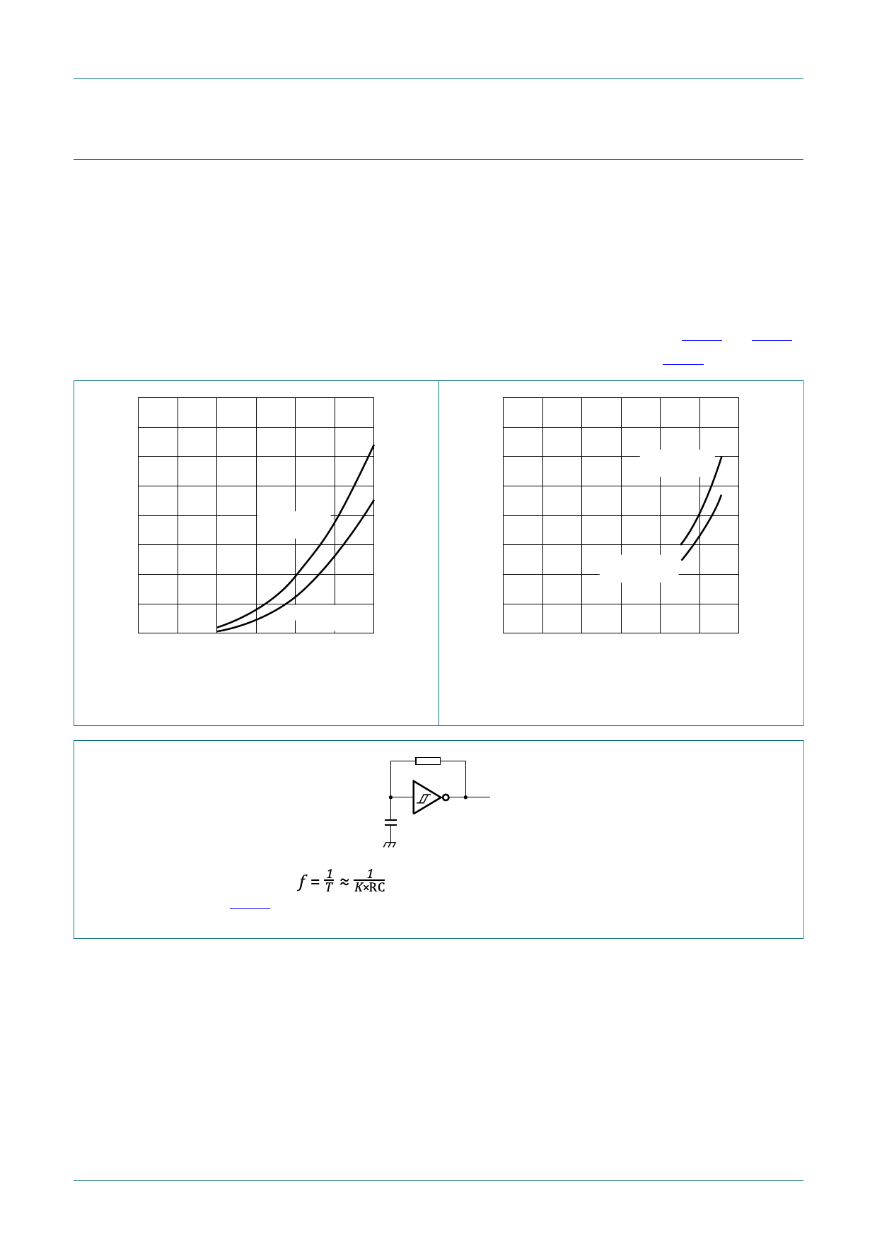
Average ΔICC(AV) differs with positive or negative input transitions, as shown in Fig. 12 and Fig. 13.
An example of a relaxation circuit using the 74HC14; 74HCT14 is shown in Fig. 14.
400
ICC(AV)
(µA)
300
mna852
400
ICC(AV)
(µA)
300
mna853
positive - going
edge
200
positive - going
edge
100
200
negative - going
100
edge
negative - going
edge
0
0
2
4 VCC (V) 6
Fig. 12. Average additional supply current
as a function of VCC for 74HC14;
linear change of VI between 0.1VCC to 0.9VCC.
0
0
2
4 VCC (V) 6
Fig. 13. Average additional supply current
as a function of VCC for 74HCT14;
linear change of VI between 0.1VCC to 0.9VCC.
R
For 74HC14 and 74HCT14:
For K-factor see Fig. 15
Fig. 14. Relaxation oscillator
C
mna035
74HC_HCT14
Product data sheet
All information provided in this document is subject to legal disclaimers.
Rev. 8 — 22 May 2020
© Nexperia B.V. 2020. All rights reserved
10 / 18
Share Link: 