MAX525BCAP 데이터 시트보기 (PDF) - Maxim Integrated
부품명
상세내역
제조사
MAX525BCAP Datasheet PDF : 16 Pages
| |||
Low-Power, Quad, 12-Bit Voltage-Output DAC
with Serial Interface
__________Applications Information
Unipolar Output
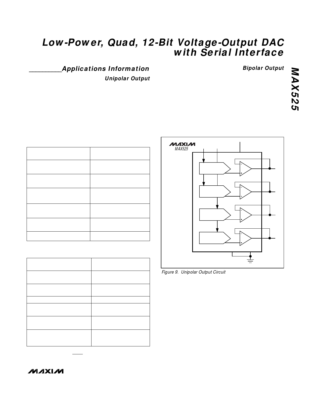
For a unipolar output, the output voltages and the refer-
ence inputs have the same polarity. Figure 9 shows the
MAX525 unipolar output circuit, which is also the typi-
cal operating circuit. Table 2 lists the unipolar output
codes.
For rail-to-rail outputs, see Figure 10. This circuit shows
the MAX525 with the output amplifiers configured with a
closed-loop gain of +2 to provide 0V to 5V full-scale
range when a 2.5V reference is used.
Table 2. Unipolar Code Table
DAC CONTENTS
MSB
LSB
1111 1111 1111
1000 0000 0001
1000 0000 0000
0111 1111 1111
0000 0000 0001
0000 0000 0000
ANALOG OUTPUT
+VREF
(
—4—09—5
4096
)
+VREF
(
—2—04—9
4096
)
+VREF ( —2—04—8 ) = —+—VR—E—F
4096
2
+VREF
(
—2—04—7
4096
)
+VREF
(
——1 —
4096
)
0V
Table 3. Bipolar Code Table
DAC CONTENTS
MSB
LSB
1111 1111 1111
1000
1000
0111
0000 0001
0000 0000
1111 1111
0000 0000 0001
0000 0000 0000
ANALOG OUTPUT
+VREF ( —22—0044—87 )
+VREF ( —2—014—8 )
0V
-VREF ( —2—014—8 )
-VREF ( —22—0044—87 )
-VREF
(
—20—4—8
2048
)
=
-VREF
Note:
1LSB
=
(VREF)
(
1
4096
)
Bipolar Output
The MAX525 outputs can be configured for bipolar
operation using Figure 11’s circuit.
VOUT = VREF [(2NB / 4096) - 1]
where NB is the numeric value of the DAC’s binary
input code. Table 3 shows digital codes (offset binary)
and corresponding output voltages for Figure 11’s
circuit.
MAX525
REFERENCE INPUTS
REFAB
REFCD
+5V
VDD
DAC A
FBA
OUTA
FBB
DAC B
OUTB
FBC
DAC C
OUTC
FBD
DAC D
AGND
DGND
OUTD
Figure 9. Unipolar Output Circuit
______________________________________________________________________________________ 13
Share Link: 