M74HCT125 데이터 시트보기 (PDF) - STMicroelectronics
부품명
상세내역
제조사
M74HCT125 Datasheet PDF : 9 Pages
| |||
M74HCT125
CAPACITIVE CHARACTERISTICS
Test Condition
Value
Symbol
Parameter
VCC
(V)
TA = 25°C
-40 to 85°C -55 to 125°C Unit
Min. Typ. Max. Min. Max. Min. Max.
CIN Input Capacitance
5 10
10
10 pF
CPD Power Dissipation
Capacitance (note
56
pF
1)
1) CPD is defined as the value of the IC’s internal equivalent capacitance which is calculated from the operating current consumption without
load. (Refer to Test Circuit). Average operating current can be obtained by the following equation. ICC(opr) = CPD x VCC x fIN + ICC
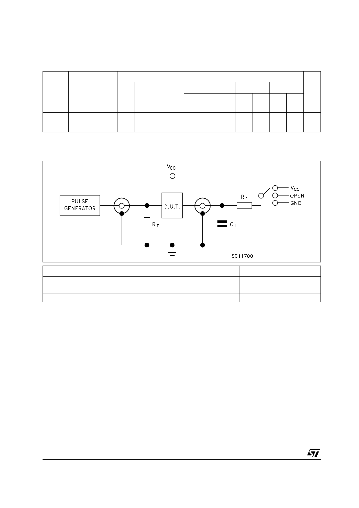
TEST CIRCUIT
TEST
tPLH, tPHL
tPZL, tPLZ
tPZH, tPHZ
CL = 50pF/150pF or equivalent (includes jig and probe capacitance)
R1 = 1KΩ or equivalent
RT = ZOUT of pulse generator (typically 50Ω))
SWITCH
Open
VCC
GND
4/9
Share Link: 