LTC1417IGN(RevA) 데이터 시트보기 (PDF) - Linear Technology
부품명
상세내역
제조사
LTC1417IGN
(Rev.:RevA)
(Rev.:RevA)
Linear Technology
LTC1417IGN Datasheet PDF : 32 Pages
| |||
LTC1417
APPLICATIONS INFORMATION
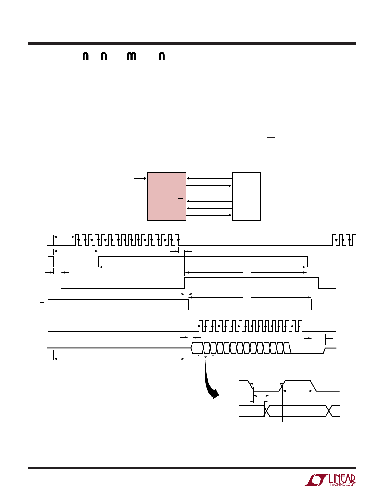
Using an External Conversion Clock and an External
Data Clock. In Figure 20, data is also output after each
conversion is completed and before the next conversion is
started. An external clock is used for the conversion clock
and either another or the same external clock is used for
the SCLK. This mode is identical to Figure 19 except that
an external clock is used for the conversion. This mode
allows the user to synchronize the A/D conversion to an
external clock either to have precise control of the internal
bit test timing or to provide a precise conversion time. As in
Figure 19, this mode works when the SCLK frequency is
very low (less than 30kHz). However, the external conver-
sion clock must be between 30kHz and 9MHz to maintain
accuracy. If more than 16 SCLKs are provided, more zeros
will be filled in after the data word indefinitely. To select the
external conversion clock, apply an external conversion
clock to EXTCLKIN. The external SCLK is applied to SCLK.
RD can be used to gate the external SCLK such that data will
be clocked out only after RD goes low.
13
CONVST
6
CONVST EXTCLKIN
14
BUSY
LTC1417
12
RD
7
SCLK
DOUT 9
CLKOUT
INT
µP OR DSP
C0
SCK
MISO
EXTCLKIN
CONVST
BUSY
RD
SCLK
DOUT
tdEXTCLKIN 1 2 3 4 5 6 7 8 9 10 11 12 13 14 15 16
t2
t4
t3
HOLD
(SAMPLE N)
Hi-Z
tCONV
1234
t10
t6
t5
SAMPLE
t9
1 2 3 4 5 6 7 8 9 10 11 12 13 14 15 16
t7
D13 12 11 10 9 8 7 6 5 4 3 2 1 0
DATA N
FILL
ZEROS
t8
Hi-Z
22
SCLK
DOUT
tLSCLK
VIL
t11
t12
D13
tHSCLK
D12
CAPTURE ON CAPTURE ON
RISING CLOCK FALLING CLOCK
VOH
D11
VOL
1417 F20
Figure 20. External Conversion Clock Selected. Data Transferred After Conversion
Using an External SCLK. BUSY↑ Indicates End of Conversion
sn1417 1417fas
Share Link: 