STPS10170C 데이터 시트보기 (PDF) - STMicroelectronics
부품명
상세내역
제조사
STPS10170C Datasheet PDF : 10 Pages
| |||
Characteristics
STPS10170C
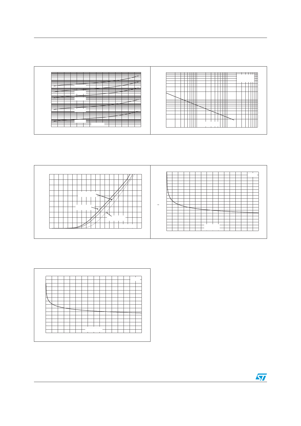
Figure 7.
Reverse leakage current versus
reverse voltage applied (typical
values, per diode)
IR(µA)
1.E+05
1.E+04
1.E+03
1.E+02
1.E+01
Tj=175°C
Tj=150°C
Tj=125°C
1.E+00
Tj=75°C
1.E-01
1.E-02
0
Tj=25°C
VR(V)
25
50
75
100
125
150
175
Figure 8.
C(pF)
1000
Junction capacitance versus
reverse voltage applied (typical
values, per diode)
F=1MHz
VOSC=30mVRMS
Tj=25°C
100
10
1
VR(V)
10
100
1000
Figure 9. Forward voltage drop versus
forward current (per diode)
IFM(A)
100.0
90.0
80.0
70.0
60.0
Tj=125°C
(Maximum values)
50.0
40.0
30.0
Tj=125°C
(Typical values)
20.0
Tj=25°C
(Maximum values)
10.0
0.0
VFM(V)
0.0 0.2 0.4 0.6 0.8 1.0 1.2 1.4 1.6 1.8 2.0
Figure 10.
Thermal resistance junction to
ambient versus copper surface
under tab (epoxy printed board
FR4, Cu = 35 µm - DPAK)
Rth( -a)(°C/W)
100
90
DPAK
80
70
60
50
40
30
20
10
0
0
SCU(cm²)
5
10
15
20
25
30
35
40
Figure 11.
Thermal resistance junction to
ambient versus copper surface
under tab (epoxy printed board
FR4, Cu = 35 µm - D2PAK)
Rth(j-a)(°C/W)
80
70
D²PAK
60
50
40
30
20
10
0
0
SCU(cm²)
5
10
15
20
25
30
35
40
4/10
Share Link: 