BKAF3-A113-40901 데이터 시트보기 (PDF) - ITT Cannon
부품명
상세내역
제조사
BKAF3-A113-40901 Datasheet PDF : 120 Pages
| |||
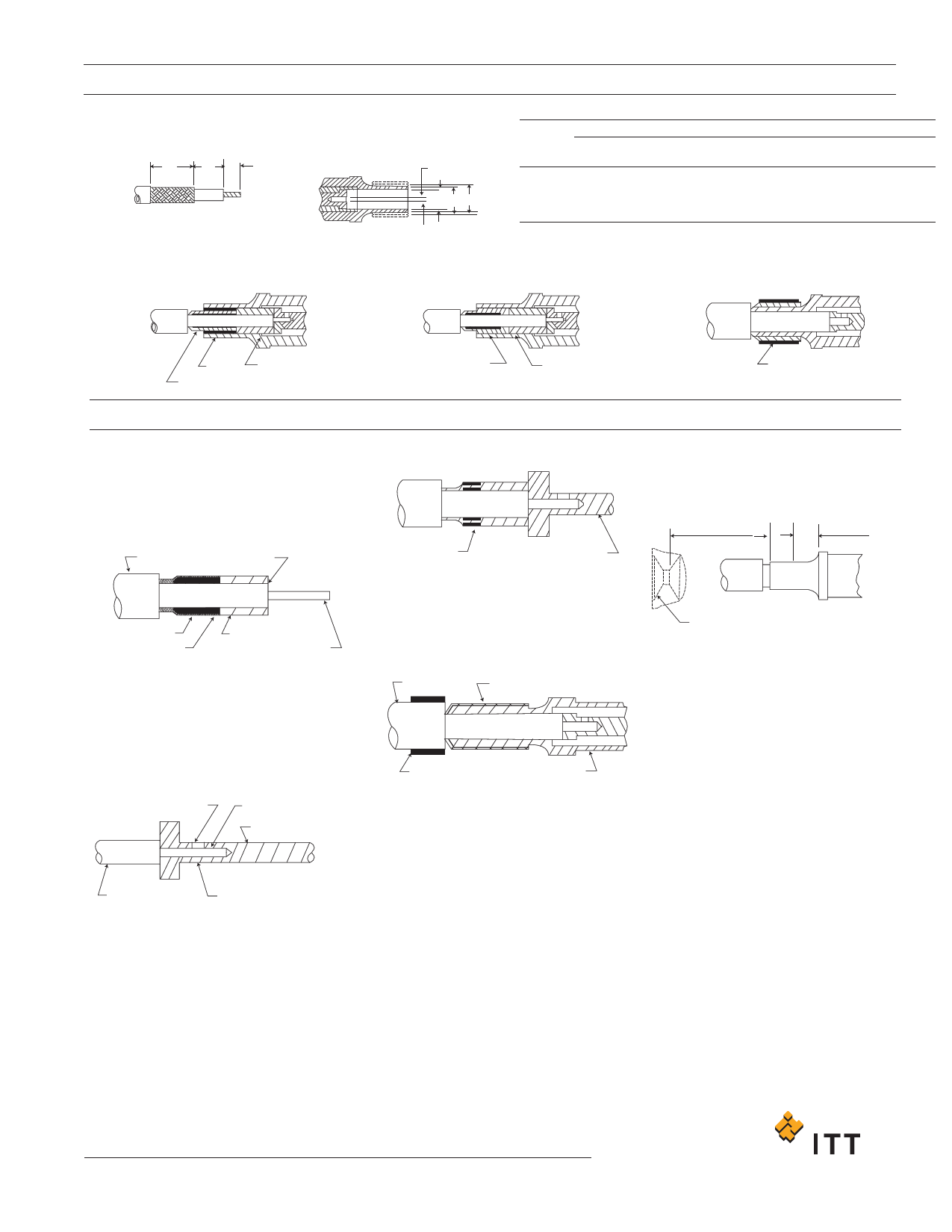
Assembly Procedures
Coaxial Contact Assembly (DPGM/DPJM)
Cable Stripping
A
BC
50 Ohm Contact (RG-196U)
(assembly steps 1,
2, 3, 4, 5 & 8)
DPGM/DPJM/DPJMB
.035 DIA
(0.89)
DE F
Cable Trim Dimensions
A
B
C
150 ohm
95 ohm
75 ohm
50 ohm
3/16 (4.76)
3/16 (4.76)
3/16 (4.76)
1/4 (6.35)
1/16 (1.59)
1/8 (3.18)
1/8 (3.18)
1/8 (3.18)
5/32 (3.97)
5/64 (1.98)
5/64 (1.98)
5/64 (1.98)
Cable Entry Dimensions
D
min. dia.
E
max. dia.
F
min. dia.
.154 (3.91)
.106 (2.69)
.122 (3.10)
.106 (2.69)
.183 (4.65)
.139 (3.53)
.158 (4.01)
.136 (3.53)
.202 (5.13)
.153 (3.89)
75 Ohm Contact (RG-187U)
(assembly steps 1,
2, 3, 5 & 8)
95 Ohm Contact (RG-195U)
(assembly steps 1,
3, 6, 7 & 8)
SHIM
CRIMP RING
Assembly Steps
BUSHING
CRIMP RING
BUSHING
1 . After the coaxial cable has been stripped to the
proper dimensions, tin the center conductor. If
O.D. of cable is less than .096 (2.44), slip
rubber bushing over wire. (50, 75 & 95 ohm)
2. Assemble crimp ring under braid and add bush-
ing to cable. (50 & 75 ohm)
JACKET
DIELECTRIC
CRIMP RING
BRAID
BUSHING
CENTER CONDUCTOR
3. The center contact is supplied loose in the
polyethylene bag. Insert the tinned conductor
into the contact. Wire must be visible through
inspection hole and dielectric pushed against
contact shoulder. For 150 ohm contact shoulder
must be flush against bushing. Heat contact
with a clean soldering iron. Avoid solder outside
contact, (50, 75, & 95 ohm)
INSPECTION HOLE
CENTER CONDUCTOR
CENTER CONTACT
4. Wrap shim around braid. (50 ohm)
SHIM
CENTER CONTACT
5. Feed cable and assembled parts into coaxial
shell. Care is required if braid is to fit smoothly
inside the shell. (50 & 75 ohm)
6. Thread crimp ring over cable. Feed center con-
tact into coaxial shell with the shell between the
dielectric and the braid. (95 ohm)
JACKET
BRAID
CRIMP RING
SHELL
CRIMP RING
7. Slip crimp over the braid. (95 ohm)
8. Crimp - crimp tool must be located 1/16
(1.58) to 5 / 64 (1.98) from shoulder of coaxial.
(50, 75 & 95 ohms)
.125 (3.18) MIN. PLUG
.063 (1.59) MIN. RECPT
.063 (1.59) EDGE OF
.078 (1.98) CRIMP TOOL
SEALING GROMMET LOACATION
DIELECTRIC
APPLY CLEAN SOLDERING IRON
Dimensions shown in inch (mm)
Specifications and dimensions subject to change
www.ittcannon.com
103
Share Link: 