MRFE6VP8600HR6 데이터 시트보기 (PDF) - Freescale Semiconductor
부품명
상세내역
제조사
MRFE6VP8600HR6 Datasheet PDF : 20 Pages
| |||
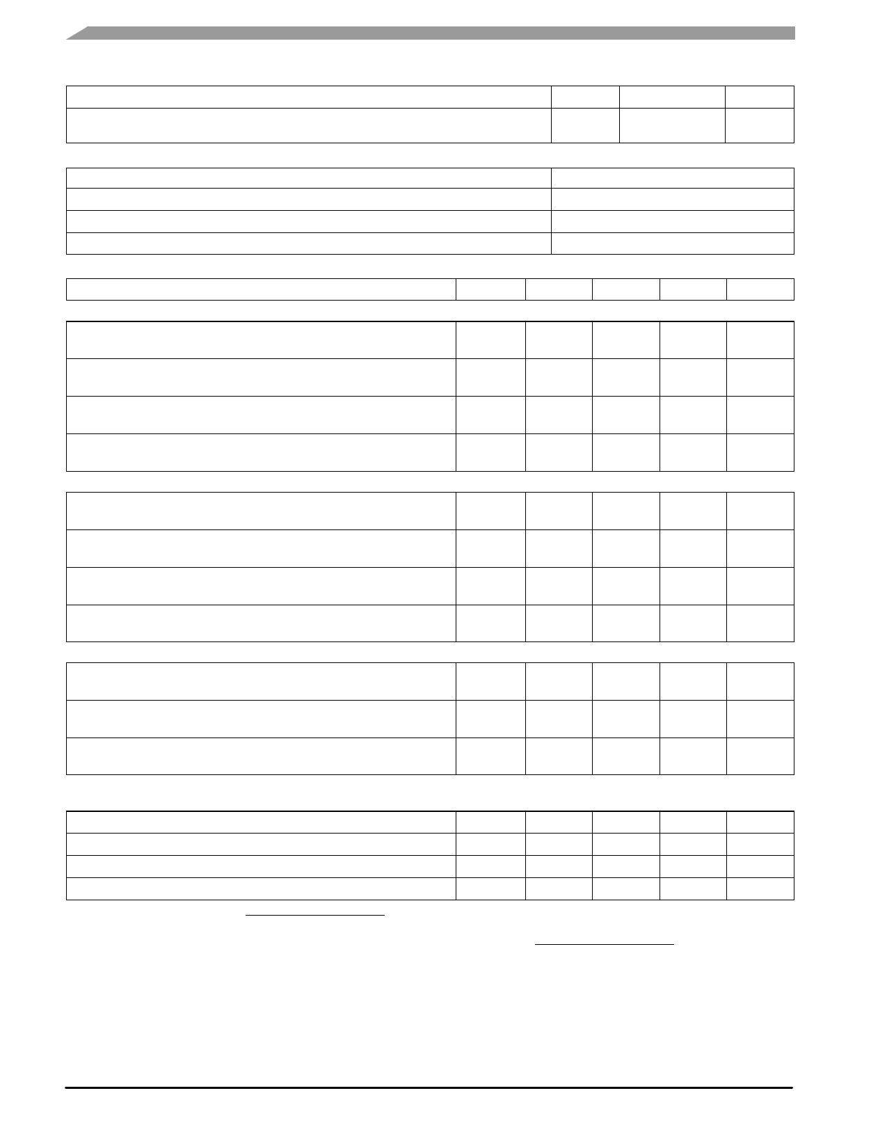
Table 2. Thermal Characteristics
Characteristic
Thermal Resistance, Junction to Case
Case Temperature 74°C, 125 W CW, 50 V, 1400 mA, 860 MHz
Symbol
RθJC
Value (1,2)
0.19 (3)
Unit
°C/W
Table 3. ESD Protection Characteristics
Test Methodology
Class
Human Body Model (per JESD22--A114)
2 (2001--4000 V)
Machine Model (per EIA/JESD22--A115)
B (201--400 V)
Charge Device Model (per JESD22--C101)
IV (>1000 V)
Table 4. Electrical Characteristics (TA = 25°C unless otherwise noted)
Characteristic
Symbol
Min
Typ
Max
Unit
Off Characteristics (4)
Gate--Source Leakage Current
(VGS = 5 Vdc, VDS = 0 Vdc)
Drain--Source Breakdown Voltage
(VGS = 0 Vdc, ID = 100 mA)
Zero Gate Voltage Drain Leakage Current
(VDS = 50 Vdc, VGS = 0 Vdc)
Zero Gate Voltage Drain Leakage Current
(VDS = 100 Vdc, VGS = 0 Vdc)
IGSS
—
—
V(BR)DSS
130
140
IDSS
—
—
IDSS
—
—
1
μAdc
—
Vdc
5
μAdc
20
μAdc
On Characteristics
Gate Threshold Voltage (4)
(VDS = 10 Vdc, ID = 980 μAdc)
VGS(th)
1.5
2.07
2.5
Vdc
Gate Quiescent Voltage (5)
(VDD = 50 Vdc, ID = 1400 mAdc, Measured in Functional Test)
VGS(Q)
2.1
2.65
3.1
Vdc
Drain--Source On--Voltage (4)
(VGS = 10 Vdc, ID = 2 Adc)
VDS(on)
—
0.24
—
Vdc
Forward Transconductance
(VDS = 10 Vdc, ID = 20 Adc)
gfs
—
15.6
—
S
Dynamic Characteristics (4)
Reverse Transfer Capacitance (6)
(VDS = 50 Vdc ± 30 mV(rms)ac @ 1 MHz, VGS = 0 Vdc)
Crss
—
1.49
—
pF
Output Capacitance (6)
(VDS = 50 Vdc ± 30 mV(rms)ac @ 1 MHz, VGS = 0 Vdc)
Coss
—
79.9
—
pF
Input Capacitance (7)
(VDS = 50 Vdc, VGS = 0 Vdc ± 30 mV(rms)ac @ 1 MHz)
Ciss
—
264
—
pF
Functional Tests (5) (In Freescale Narrowband Test Fixture, 50 ohm system) VDD = 50 Vdc, IDQ = 1400 mA, Pout = 125 W Avg., f = 860 MHz,
DVB--T (8k OFDM) Single Channel. ACPR measured in 7.61 MHz Signal Bandwidth @ ±4 MHz Offset with an Integration Bandwidth of 4 kHz.
Power Gain
Gps
18.0
19.3
21.0
dB
Drain Efficiency
ηD
29.0
30.0
—
%
Adjacent Channel Power Ratio
ACPR
—
--60.5
--58.5
dBc
Input Return Loss
IRL
—
--12
--9
dB
1. MTTF calculator available at http://www.freescale.com/rf. Select Software & Tools/Development Tools/Calculators to access MTTF
calculators by product.
2. Refer to AN1955, Thermal Measurement Methodology of RF Power Amplifiers. Go to http://www.freescale.com/rf.
Select Documentation/Application Notes -- AN1955.
3. Performance with thermal grease TIM (thermal interface material) will typically degrade by 0.05°C/W due to the increased thermal contact
resistance of this TIM.
4. Each side of device measured separately.
5. Measurement made with device in push--pull configuration.
6. Part internally input matched.
7. Die capacitance value without internal matching.
(continued)
MRFE6VP8600HR6 MRFE6VP8600HR5 MRFE6VP8600HSR6 MRFE6VP8600HSR5
RF Device Data
2
Freescale Semiconductor
Share Link: 