NCP1377BDR2G 데이터 시트보기 (PDF) - ON Semiconductor
부품명
상세내역
제조사
NCP1377BDR2G Datasheet PDF : 16 Pages
| |||
Drain
Signal
NCP1377, NCP1377B
Timeout
Signal
Drain
Signal
Demag Restart
Current Sense and Timeout Restart
Timeout
Signal
5 ms
5 ms
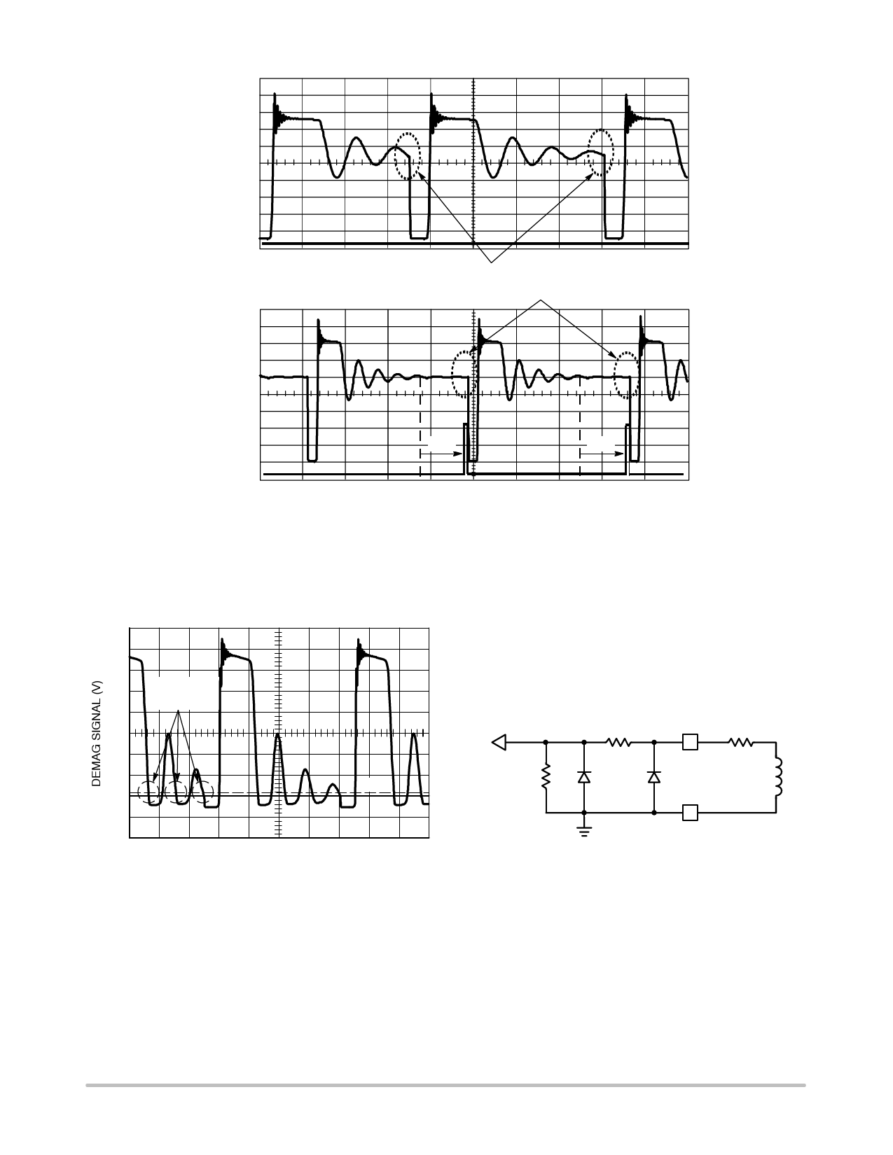
Figure 20. When the primary natural ringing becomes too low, the internal TimeOut
together with the sense comparator initiates a new cycle when FB passes the skip level.
Demagnetization Detection
The core reset detection is done by monitoring the
voltage activity on the auxiliary winding. This voltage
features a FLYBACK polarity. The typical detection level
is fixed at 50 mV as exemplified by Figure 21.
7.0
5.0
POSSIBLE
RESTARTS
3.0
1.0
0V
−1.0
50 mV
Figure 21. Core Reset Detection is Done through
a Dedicated Auxiliary Winding Monitoring
An internal timer prevents any restart within 8.0 ms
further to the driver going−low transition for NCP1377,
and 3.0 ms for NCP1377B. This prevents the switching
frequency to exceed (1.0/TON + Tblank) but also avoid false
TO INTERNAL
COMPARATOR
Rint
Resd
2
ESD2
1
1
ESD1
Rdem
5
4
Resd + Rint = 28 k
Figure 22. Internal Pad Implementation
4
Aux
3
leakage inductance tripping at turn−off. In some cases, the
leakage inductance kick is so energetic, that a slight
filtering is necessary.
http://onsemi.com
9
Share Link: 