ADUM6404ARWZ 데이터 시트보기 (PDF) - Analog Devices
부품명
상세내역
제조사
ADUM6404ARWZ Datasheet PDF : 28 Pages
| |||
ADuM6400/ADuM6401/ADuM6402/ADuM6403/ADuM6404
Data Sheet
INSULATION CHARACTERISTICS
IEC 60747-5-2 (VDE 0884 Part 2):2003-01 and DIN V VDE V 0884-10 (VDE V 0884-10):2006-12
These isolators are suitable for reinforced electrical isolation only within the safety limit data. Maintenance of the safety data is ensured by
protective circuits. The asterisk (*) marking branded on the components designates IEC 60747-5-2 (VDE 0884 Part 2):2003-01 or DIN V
VDE V 0884-10 (VDE V 0884-10):2006-12 approval.
Table 17.
Description
Installation Classification per DIN VDE 0110
For Rated Mains Voltage ≤ 300 V rms
For Rated Mains Voltage ≤ 450 V rms
For Rated Mains Voltage ≤ 600 V rms
Climatic Classification
Pollution Degree per DIN VDE 0110, Table 1
Maximum Working Insulation Voltage
Input-to-Output Test Voltage
Method b1
Method a
After Environmental Tests Subgroup 1
After Input and/or Safety Tests
Subgroup 2 and Subgroup 3
Highest Allowable Overvoltage
Safety-Limiting Values
Case Temperature
Side 1 Current (IDD1)
Insulation Resistance at TS
Test Conditions/Comments
Symbol
VIORM
VIORM × 1.875 = VPR, 100% production test, tm = 1 sec, VPR
partial discharge < 5 pC
VPR
VIORM × 1.6 = VPR, tm = 60 sec, partial discharge < 5 pC
VIORM × 1.2 = VPR, tm = 60 sec, partial discharge < 5 pC
Transient overvoltage, tTR = 10 sec
Maximum value allowed in the event of a failure
(see Figure 7)
VIO = 500 V
VIOTM
TS
IS1
RS
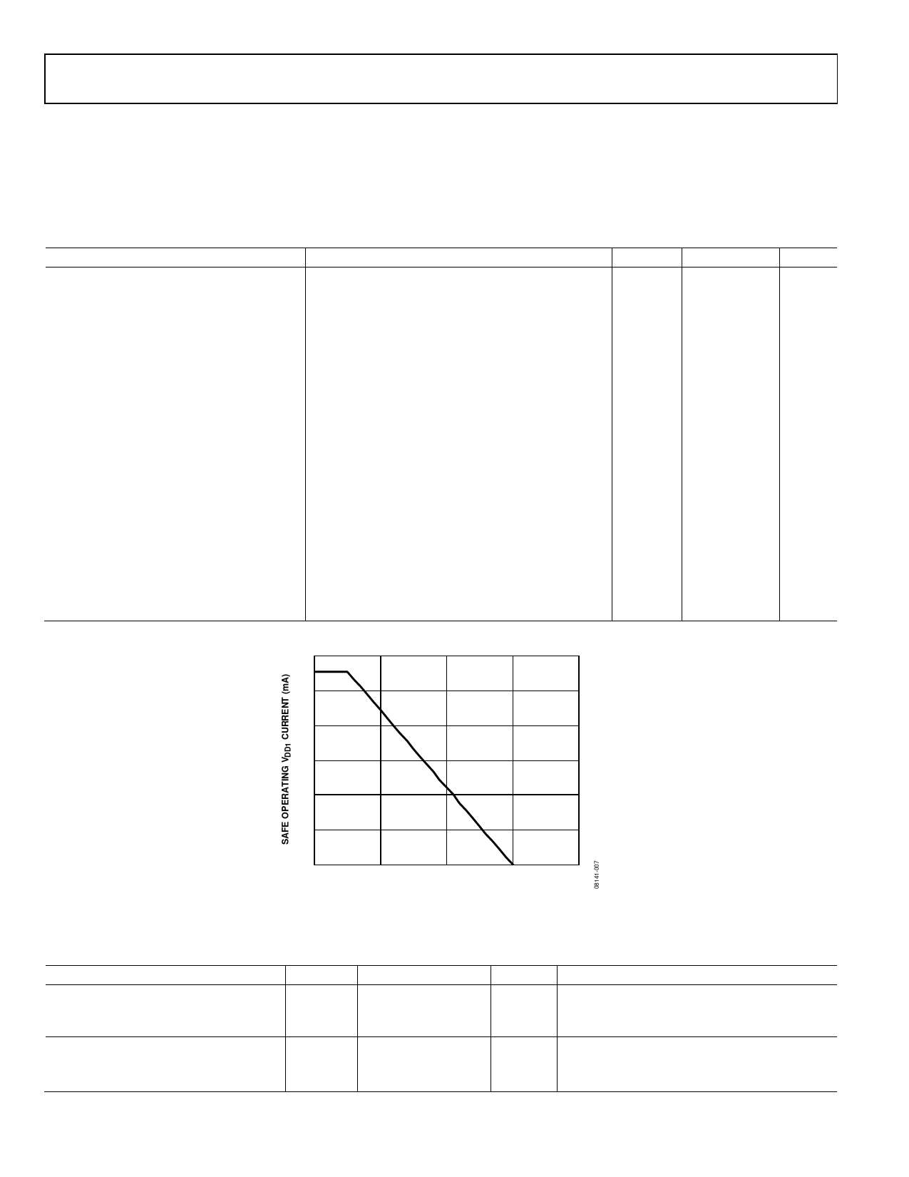
Thermal Derating Curve
600
Characteristic Unit
I to IV
I to II
I to II
40/105/21
2
846
V peak
1590
V peak
1375
1018
6000
V peak
V peak
V peak
150
°C
555
mA
>109
Ω
500
400
300
200
100
0
0
50
100
150
200
AMBIENT TEMPERATURE (°C)
Figure 7. Thermal Derating Curve, Dependence of Safety-Limiting Values on Case Temperature, per DIN EN 60747-5-2
RECOMMENDED OPERATING CONDITIONS
Table 18.
Parameter
TEMPERATURE
Operating Temperature
SUPPLY VOLTAGES
VDD1 @ VSEL = GNDISO
VDD1 @ VSEL = VISO
Symbol Min
TA
−40
VDD1
3.0
4.5
Max
Unit
+105
°C
5.5
V
5.5
V
Test Conditions/Comments
Operation at 105°C requires reduction of the
maximum load current as specified in Table 19
Each voltage is relative to its respective ground
Rev. A | Page 10 of 28
Share Link: 