OP270GSZ-REEL2 데이터 시트보기 (PDF) - Analog Devices
부품명
상세내역
제조사
OP270GSZ-REEL2 Datasheet PDF : 20 Pages
| |||
OP270
For reference, typical source resistances of some signal sources are listed in Table 5.
Table 5. Typical Source Resistances
Device
Strain Gage
Magnetic Tapehead, Microphone
Magnetic Phonograph Cartridge
Linear Variable Differential Transformer
Source Impedance
<500 Ω
<1500 Ω
<1500 Ω
<1500 Ω
Comments
Typically used in low frequency applications.
Low IB is very important to reduce self-magnetization problems when
direct coupling is used. OP270 IB can be disregarded.
Low IB is important to reduce self-magnetization problems in direct-coupled
applications. OP270 does not introduce any self-magnetization problems.
Used in rugged servo-feedback applications. The bandwidth of interest is
400 Hz to 5 kHz.
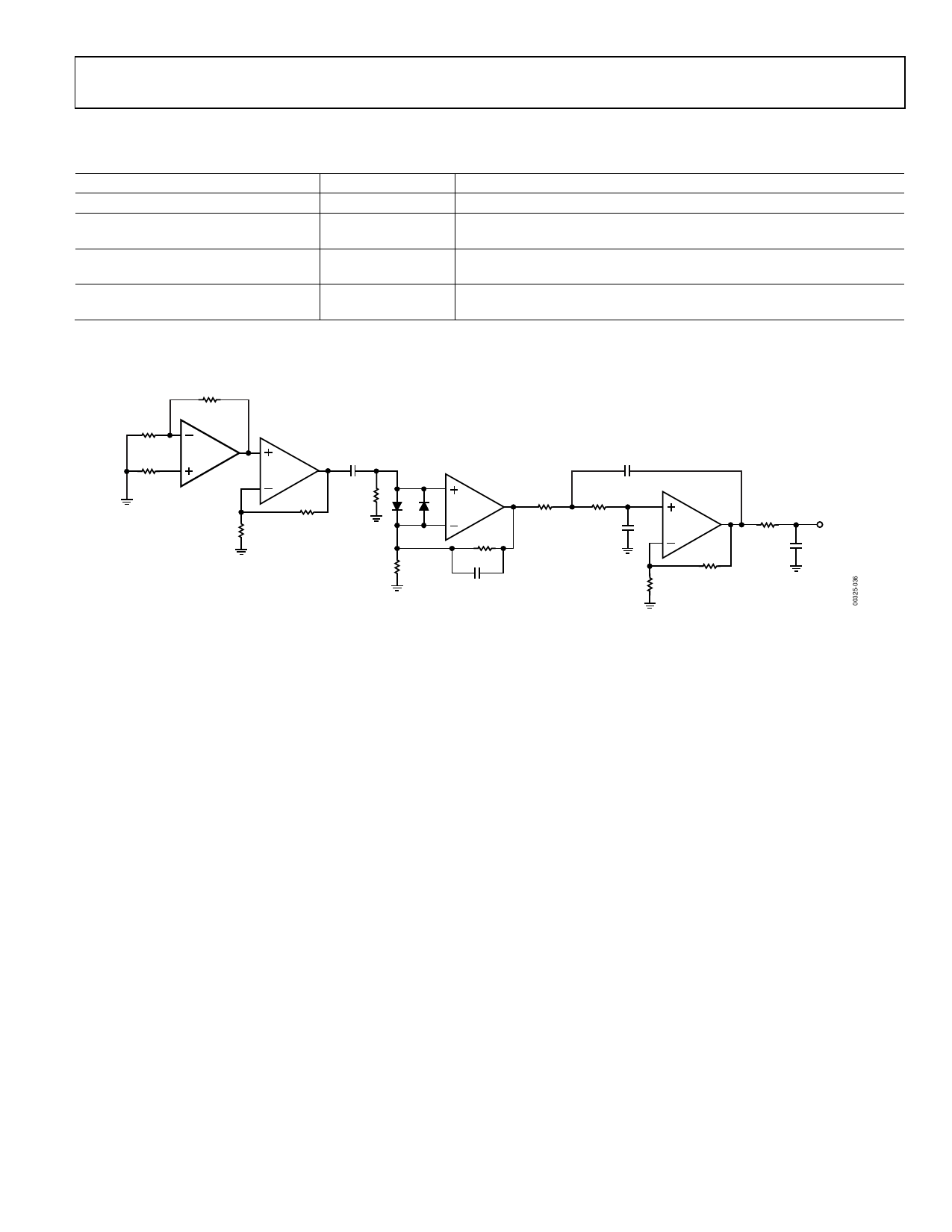
R3
1.24kΩ
R1
5Ω
R2
OP270
5Ω
DUT
OP27E
R5
909Ω
C1
2µF
R6
600Ω
D1, D2
1N4148
OP27E
R4
200Ω
R9
306Ω
R8
10kΩ
C2
0.032µF
C4
0.22µF
R10
65.4kΩ
R11
65.4kΩ
C3
0.22µF
R12
10kΩ
OP42E
R13
5.9kΩ
R14
4.99kΩ
C5
1µF
eOUT
GAIN = 50,000
VS = ±15V
Figure 35. Peak-to-Peak Voltage Noise Test Circuit (0.1 Hz to 10 Hz)
Rev. E | Page 13 of 20
Share Link: 