WL-1A100P1 데이터 시트보기 (PDF) - OMRON Corporation
부품명
상세내역
제조사
WL-1A100P1 Datasheet PDF : 23 Pages
| |||
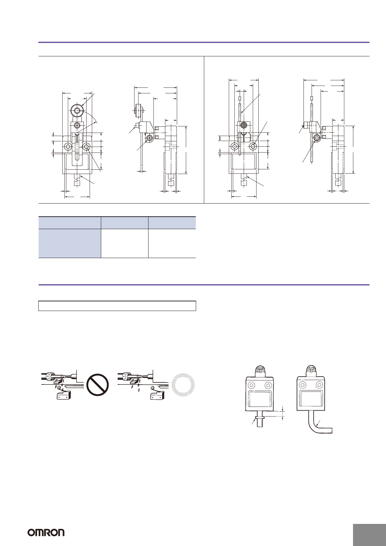
D4C
Weather-resistant Models
Adjustable Roller Lever
D4C-@@27-P
40 max.
25±0.1
17.5 dia. x 7 stainless
steel roller
57.7 max.
52.3±0.8
31.5±0.8
Adjustable Rod Lever
D4C-@@29-P
40 max.
25±0.1
5.4
3 dia. x 160 stainless
steel lever
55 max.
44
31.5
16
30R to 75R (variable)
7
11.4 M5 (length: 16)
Allen-head bolt
7.5
8 M5 (length: 12)
Allen-head bolt
2
23
65 max.
Two,
5.1
+0.2
0
dia.
holes
2
Spot facing 10.2 dia. Depth: 6
VCTF cable, 0.75 mm2,
2
4 conductor Finishing O.D.: 7.6 1.4
1.5
34
7
2
2
34
Two,
5.1
+0.2
0
dia.
holes
Spot facing 10.2 dia.
Depth: 6
11.4
7.5
8
23
M5 (length: 16)
Allen-head bolt
M5 (length: 12)
Allen-head bolt
16
65 max.
VCTF cable, 0.75 mm2,
4 conductor Finishing O.D.: 7.6 1.4
1.5
Note: Unless otherwise specified, a tolerance of ±0.4 mm applies to all dimensions.
Operating
characteristics
Model
D4C-@@27-P
D4C-@@29-P *
Operating force OF
Release force RF
Pretravel
PT
Overtravel
OT
Movement Differential MD
max.
min.
max.
min.
max.
5.69 N
1.47 N
25°
40°
3°
5.69 N
1.47 N
25°
40°
3°
* Operation characteristics for the D4C-@@27-P and D4C- @@29-P are for a lever length of 38 mm.
Safety Precautions
For details, be sure to read Safety Precautions for All Limit Switches.
Precautions for Correct Use
Operating Environment
• Seal material may deteriorate if a Switch is used outdoor or where
subject to special cutting oils, solvents, or chemicals. Always
appraise performance under actual application conditions and set
suitable maintenance and replacement periods.
• Install Switches where they will not be directly subject to cutting
chips, dust, or dirt. The Actuator and Switch must also be protected
from the accumulation of cutting chips or sludge.
Not Suitable
Suitable
Handling
The bottom of the Switch at the cable outlet is resin-molded. Secure
the cable at a point 5 cm from the Switch bottom to prevent exertion
of excess force on the cable.
When bending the cable, provide a bending radius of 45 mm min. so
as not to damage the cable insulation or sheath. Excessive bending
may cause fire or leakage current.
• Constantly subjecting a Switch to vibration or shock can result in
wear, which can lead to contact interference with contacts,
operation failure, reduced durability, and other problems.
Excessive vibration or shock can lead to false contact operation or
damage. Install Switches in locations not subject to shock and
vibration and in orientations that will not produce resonance.
• The Switches have physical contacts. Using them in environments
containing silicon gas will result in the formation of silicon oxide
(SiO2) due to arc energy. If silicon oxide accumulates on the
contacts, contact interference can occur. If silicon oil, silicon filling
agents, silicon cables, or other silicon products are present near the
Switch, suppress arcing with contact protective circuits (surge
killers) or remove the source of silicon gas.
Secure
here
5 cm
Bending radius
(R45 mm min.)
Connections
• Be sure to connect a fuse with a breaking current 1.5 to 2 times
larger than the rated current to the Limit Switch in series in order to
protect the Limit Switch from damage due to short-circuiting.
• When using the Limit Switch for the EN ratings, use the gI or gG 10-
A fuse.
http://www.ia.omron.com/
(c)Copyright OMRON Corporation 2007 All Rights Reserved.
13
Share Link: 