TDA9800T 데이터 시트보기 (PDF) - Philips Electronics
부품명
상세내역
제조사
TDA9800T Datasheet PDF : 23 Pages
| |||
Philips Semiconductors
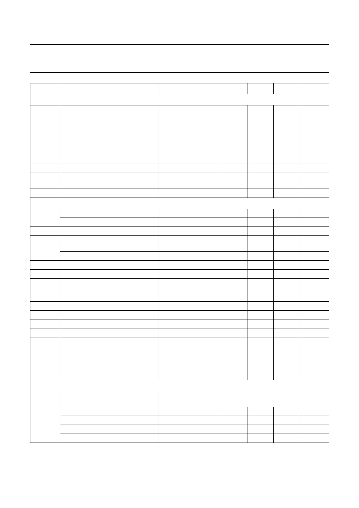
VIF-PLL demodulator and FM-PLL detector
Preliminary specification
TDA9800
SYMBOL
PARAMETER
CONDITIONS
MIN. TYP. MAX. UNIT
FM sound limiter amplifier (pin 11)
note 17
Vi FM
αAM
R11
B
input signal (RMS value, pin 11)
CCIR468-4
for S/N = 40 dB
see Fig.11
−
200
300
µV
for AM suppression αAM = 40 dB AM: f = 1 kHz; m = 0.3 −
1
−
mV
maximum input signal handling
200
−
−
mV
(RMS value)
AM suppression
see Fig.10;
46
50
−
dB
AM: f = 1 kHz; m = 0.3
input resistance
480
600
720
Ω
−3 dB IF frequency response of
sound IF
lower and upper
cut-off frequency
3.5
−
10
MHz
V11
DC voltage
2.3
2.6
2.9
V
FM-PLL sound demodulator and AF output (pin 9) note 17
fi FM
catching range of PLL
4
−
7
MHz
holding range of PLL
3.5
−
8
MHz
tacqu
Vo AF
acquisition time
AF output signal (RMS value, pin 9)
∆fAF = ±27 kHz;
see Fig.11
−
−
4
µs
280
350
420
mV
maximum output signal handling
THD < 1.5%
0.8
−
−
V
∆Vo
temperature drift of AF output signal
−
3
∆fAF
frequency deviation
THD < 1.5%; note 18 −
−
V10
DC voltage at decoupling capacitor voltage dependent on 1.2
−
VCO frequency;
note 19
7
10-3 dB/K
±50
kHz
2.2
V
R9
output resistance
RL
load resistance (pin 9)
−
100
−
Ω
2.2
−
−
kΩ
V9
DC voltage
B
−3 dB audio frequency bandwidth
1.6
2.0
2.4
V
95
120
−
kHz
THD
total harmonic distortion
without ceramic filter −
0.1
0.5
%
S/N (W) signal-to-noise ratio, weighted
CCIR468-4; see Fig.11 50
55
−
dB
VSC
residual sound carrier and
harmonics (RMS value)
−
−
75
mV
RR
ripple rejection on pin 9
see Fig.9
26
30
−
dB
Measurements from IF input to audio output (pin 9) 560 Ω between pins 13 and 11; note 20
S/N (W) weighted signal-to-noise ratio
6 kHz sinusoidal waveform
black picture
white picture
colour bar
27 kHz FM deviation; CCIR468-4; 50 µs (75 µs at standard M)
de-emphasis; with offset alignment on pin 4
black-to-white
39
46
−
dB
sync only
40
48
−
dB
39
46
−
dB
39
46
−
dB
July 1994
11
Share Link: 