STK672-210 데이터 시트보기 (PDF) - SANYO -> Panasonic
부품명
상세내역
제조사
STK672-210
SANYO -> Panasonic
STK672-210 Datasheet PDF : 8 Pages
| |||
STK672-210
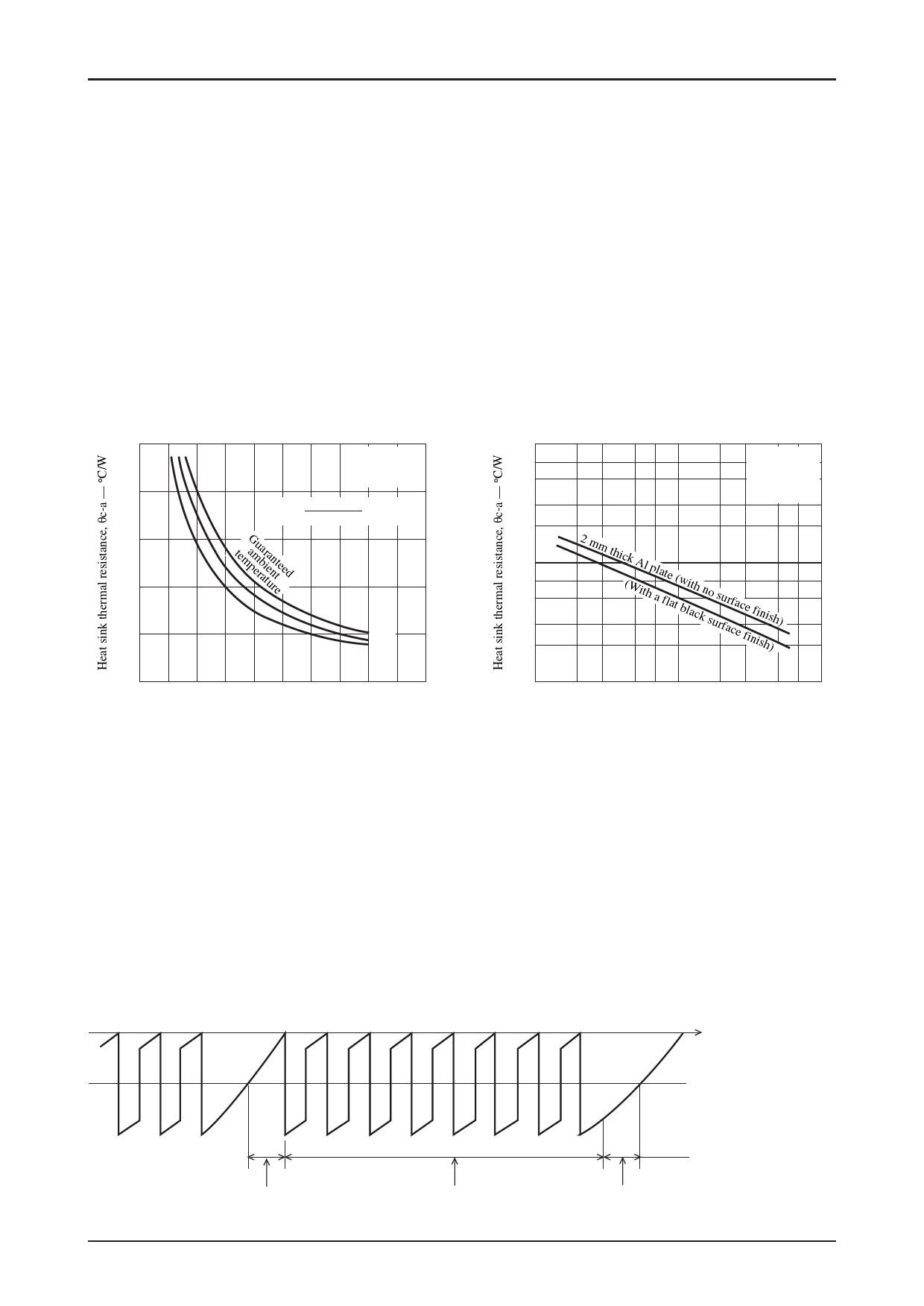
Thermal Design
The size of the heat sink required for the STK672-210 depends on the motor output current IOH (A), the electrical
characteristics of the motor, the excitation mode, and the basic drive frequency.
The thermal resistance (θc-a) of the required heat sink can be determined from the following formula.
θc – a = —T—c m—ax—–—T—a (°C/W)
Pd
Tcmax: The STK672-210 substrate temperature (°C)
Ta: The STK672-210 ambient temperature (°C)
Pd: The average internal power dissipation in the STK672-210 (W)
For example, the required area for a heat sink made from 2 mm thick aluminum can be determined from the graph at the
right below. Note that the ambient temperature is greatly influenced by the ventilation and air flow patterns within the
application. This means that the size of the heat sink must be determined with care so that the STK672-210 back surface
(aluminum substrate) temperature Tc in the mounted state never exceeds, under any conditions that might occur, the
temperature Tc = 105 °C.
θc-a — Pd
θc-a — S
20
100
No Fin
No Fin
23.0[°C / W]
7
23.0[°C / W]
Tc max=105°C
5
16
θc-a=
Tc
max--Ta
Pd
(°C
/
W)
3
2
Mounted vertically
Convection cooling
12
8
temaGpmeurbaairteaunnretteed
40°C
4
50°C
60°C
10
7
5
3
2
2 mm thic(kWAitlhpalaftleat(wbliathcknsousrufarcfaecfeinfiisnhis)h)
0
0 2 4 6 8 10 12 14 16 18 20
IC internal average power dissipation, Pd — W
ITF01880
STK672-210 Average Internal Power Dissipation Pd
1.0
10
23
5 7 100
23
Heat sink area, S — cm2
5 7 1000
ITF01881
Of the devices that contribute to the STK672-210 average internal power supply, the devices with the largest power
dissipation are the current control devices, the diodes that handle the regenerative current, the current detection resistor,
and the predriver circuit.
The following presents formulas for calculating the power dissipation for the different excitation (drive) modes.
2 phase excitation mode
Pd2EX = (Vsat + Vdf) × 0.5 × Clock × IOH × t2 + 0.5 × Clock × IOH × (Vsat × t1 + Vdf × t3)
1-2 phase excitation mode
Pd1-2EX = (Vsat + Vdf) × 0.25 × Clock × IOH × t2 + 0.25 × Clock × IOH × (Vsat × t1 + Vdf × t3)
Motor hold mode
PdHOLDEX = (Vsat + Vdf) × IOH
Vsat: Ron voltage drop + shunt resistor combined voltage
Vdf: FET internal diode Vdf + shunt resistor combined voltage
Clock: Input clock CLK (the reference frequency prior to splitting into 4 phases)
IOH
0A
t1
t2
t3
ITF02290
Figure 1 Motor Output Current Waveform Model (Commutation Current)
No.7464-6/8
Share Link: 