SI4702-C19 데이터 시트보기 (PDF) - Silicon Laboratories
부품명
상세내역
제조사
SI4702-C19 Datasheet PDF : 46 Pages
| |||
Si4702/03-C19
and Antenna Interface". Conformance to these
guidelines will help to ensure excellent performance
even in weak signal or noisy environments.
An image-reject mixer downconverts the RF signal to
low-IF. The quadrature mixer output is amplified,
filtered, and digitized with high resolution
analog-to-digital converters (ADCs). This advanced
architecture achieves superior performance by using
digital signal processing (DSP) to perform channel
selection, FM demodulation, and stereo audio
processing compared to traditional analog
architectures.
4.3. General Purpose I/O Pins
The pins GPIO1–3 can serve multiple functions. GPIO1
and GPIO3 can be used to select between 2-wire and
3-wire modes for the control interface as the device is
brought out of reset. See Section “4.9. Reset, Powerup,
and Powerdown”. After powerup of the device, the
GPIO1–3 pins can be used as general purpose
inputs/outputs, and the GPIO2–3 pins can be used as
interrupt request pins for the seek/tune or RDS ready
functions and as a stereo/mono indicator respectively.
See register 04h, bits [5:0] in Section “6. Register
Descriptions” for information on the control of these
pins. It is recommended that the GPIO2–3 pins not be
used as interrupt request outputs until the powerup time
has completed (see Section “4.9. Reset, Powerup, and
Powerdown”). The GPIO3 pin has an internal, 1 M,
±15% pull-down resistor that is only active while RST is
low. General purpose input/output functionality is
available regardless of the state of the VA and VD
supplies, or the ENABLE and DISABLE bits.
(RDSS) and block error rate A, B, C and D (BLERA,
BLERB, BLERC, and BLERD) are unused and will read
0. This mode is backward compatible with earlier
firmware revisions.
Setting the RDS mode bit high places the device in RDS
verbose mode. The device sets RDSS high when
synchronized and low when synchronization is lost. If
the device is synchronized, RDS ready (RDSR) will be
set for a minimum of 40 ms when a RDS group has
been received. Setting the RDS interrupt enable
(RDSIEN) bit and GPIO2[1:0] = 01 will configure GPIO2
to pulse low for a minimum of 5 ms if the device is
synchronized and an RDS group has been received.
BLERA, BLERB, BLERC and BLERD provide
block-error levels for the RDS group. The number of bit
errors in each block within the group is encoded as
follows: 00 = no errors, 01 = one to two errors,
10 = three to five errors, 11 = six or more errors. Six or
more errors in a block indicate the block is
uncorrectable and should not be used.
*Note: RDS/RBDS is referred to only as RDS throughout the
remainder of this document.
4.5. Stereo Audio Processing
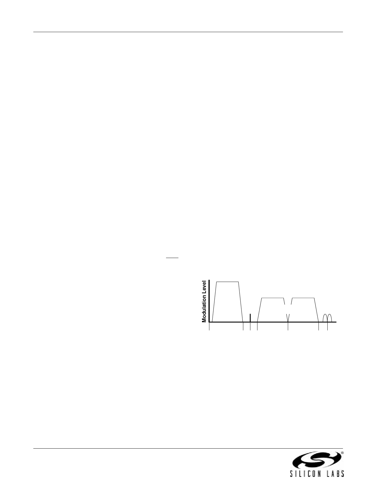
The output of the FM demodulator is a stereo
multiplexed (MPX) signal. The MPX standard was
developed in 1961 and is used worldwide. Today's MPX
signal format consists of left + right (L+R) audio, left –
right (L–R) audio, a 19 kHz pilot tone, and RDS/RBDS
data as shown in Figure 8.
4.4. RDS/RBDS Processor and
Functionality
The Si4703 implements an RDS/RBDS* processor for
symbol decoding, block synchronization, error
detection, and error correction. RDS functionality is
enabled by setting the RDS bit. The device offers two
RDS modes, a standard mode and a verbose mode.
The primary difference is increased visibility to RDS
block-error levels and synchronization status with
verbose mode.
Setting the RDS mode (RDSM) bit low places the
device in standard RDS mode (default). The device will
set the RDS ready (RDSR) bit for a minimum of 40 ms
when a valid RDS group has been received. Setting the
RDS interrupt enable (RDSIEN) bit and GPIO2[1:0] = 01
will configure GPIO2 to pulse low for a minimum of 5 ms
when a valid RDS group has been received. If an invalid
group is received, RDSR will not be set and GPIO2 will
not pulse low. In standard mode RDS synchronization
Mono Audio
Left + Right
Stereo
Pilot
Stereo Audio
Left - Right
RDS/
RBDS
0
15 19 23
38
53 57
Frequency (kHz)
Figure 8. MPX Signal Spectrum
The Si4702/03-C19's integrated stereo decoder
automatically decodes the MPX signal. The 0 to 15 kHz
(L+R) signal is the mono output of the FM tuner. Stereo
is generated from the (L+R), (L-R), and a 19 kHz pilot
tone. The pilot tone is used as a reference to recover
the (L-R) signal. Separate left and right channels are
obtained by adding and subtracting the (L+R) and (L-R)
signals, respectively. The Si4703-C uses frequency
information from the 19 kHz stereo pilot to recover the
57 kHz RDS/RBDS signal.
Adaptive noise suppression is employed to gradually
16
Rev. 1.1
Share Link: 