PCF8578 데이터 시트보기 (PDF) - Philips Electronics
부품명
상세내역
제조사
PCF8578 Datasheet PDF : 48 Pages
| |||
Philips Semiconductors
LCD row/column driver for
dot matrix graphic displays
Product specification
PCF8578
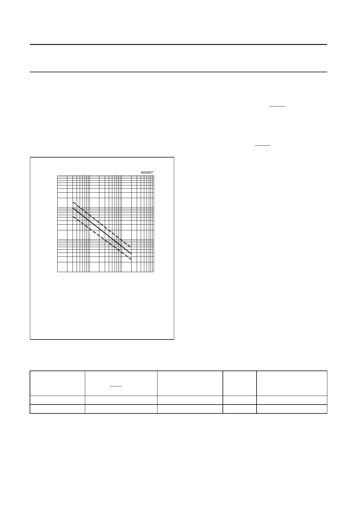
7.5 Internal clock
The clock signal for the system may be generated by the
internal oscillator and prescaler. The frequency is
determined by the value of the resistor ROSC, see Fig.9.
For normal use a value of 330 kΩ is recommended.
The clock signal, for cascaded PCF8579s, is output at
CLK and has a frequency 1⁄6 (multiplex rate 1 : 8, 1 : 16
and 1 : 32) or 1⁄8 (multiplex rate 1 : 24) of the oscillator
frequency.
10 3
f OSC
(kHz)
10 2
MSA837
10
1
10
102
103
104
R OSC (kΩ )
To avoid capacitive coupling, which could adversely affect oscillator
stability, ROSC should be placed as closely as possible to the OSC
pin. If this proves to be a problem, a filtering capacitor may be
connected in parallel to ROSC.
Fig.9 Oscillator frequency as a function of
external oscillator resistor, ROSC.
7.6 External clock
If an external clock is used, OSC must be connected to
VDD and the external clock signal to CLK. Table 4
summarizes the nominal CLK and SYNC frequencies.
7.7 Timing generator
The timing generator of the PCF8578 organizes the
internal data flow of the device and generates the LCD
frame synchronization pulse SYNC, whose period is an
integer multiple of the clock period. In cascaded
applications, this signal maintains the correct timing
relationship between the PCF8578 and PCF8579s in the
system.
7.8 Row/column drivers
Outputs R0 to R7 and C32 to C39 are fixed as row and
column drivers respectively. The remaining 24 outputs
R8/C8 to R31/C31 are programmable and may be
configured (in blocks of 8) to be either row or column
drivers. The row select signal is produced sequentially at
each output from R0 up to the number defined by the
multiplex rate (see Table 1). In mixed mode the remaining
outputs are configured as columns. In row mode all
programmable outputs (R8/C8 to R31/C31) are defined as
row drivers and the outputs C32 to C39 should be left
open-circuit.
Using a 1 : 16 multiplex rate, two sets of row outputs are
driven, thus facilitating split-screen configurations, i.e. a
row select pulse appears simultaneously at R0 and
R16/C16, R1 and R17/C17 etc. Similarly, using a multiplex
rate of 1 : 8, four sets of row outputs are driven
simultaneously. Driver outputs must be connected directly
to the LCD. Unused outputs should be left open-circuit.
In 1 : 8 R0 to R7 are rows; in 1 : 16 R0 to R15/C15 are
rows; in 1 : 24 R0 to R23/C23 are rows; in 1 : 32
R0 to R31/C31 are rows.
Table 4 Signal frequencies required for nominal 64 Hz frame frequency; note 1.
OSCILLATOR
FREQUENCY
fOSC(2) (Hz)
12 288
12 288
FRAME FREQUENCY
fSYNC (Hz)
64
64
MULTIPLEX RATE (n)
DIVISION
RATIO
1 : 8, 1 : 16, 1 : 32
6
1 : 24
8
CLOCK FREQUENCY
fCLK (Hz)
2 048
1 536
Notes
1. A clock signal must always be present, otherwise the LCD may be frozen in a DC state.
2. ROSC = 330 kΩ.
2003 Apr 14
14
Share Link: 