PCA9507D 데이터 시트보기 (PDF) - NXP Semiconductors.
부품명
상세내역
제조사
PCA9507D Datasheet PDF : 20 Pages
| |||
NXP Semiconductors
PCA9507
2-wire serial bus extender for HDMI DDC I2C-bus and SMBus
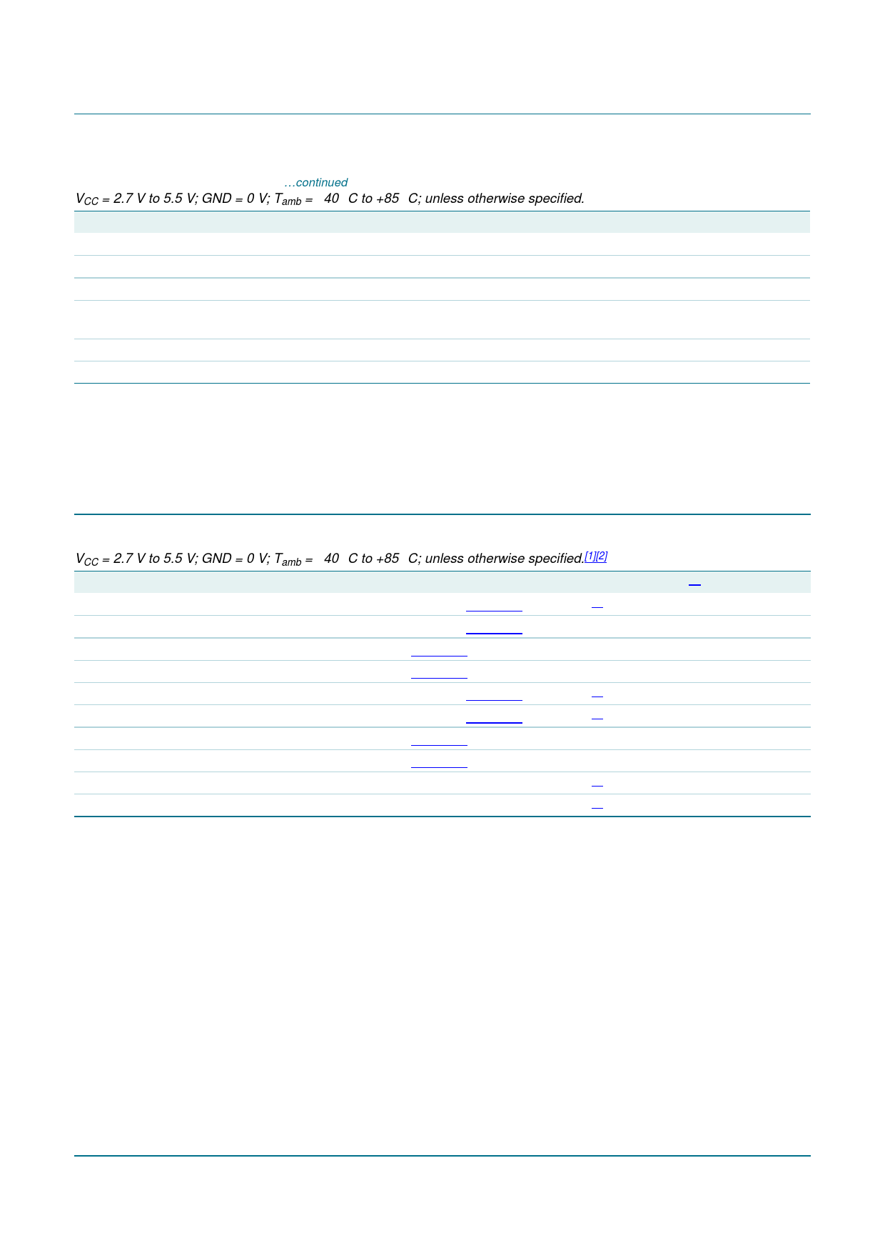
Table 5. Static characteristics …continued
VCC = 2.7 V to 5.5 V; GND = 0 V; Tamb = −40 °C to +85 °C; unless otherwise specified.
Symbol Parameter
Conditions
Min
Typ
Enable
VIL
VIH
IIL(EN)
LOW-level input voltage
HIGH-level input voltage
LOW-level input current on pin
EN
VI = 0.2 V, EN; VCC = 3.6 V
−0.5
-
0.7VCC(B) -
-
−10
ILI
input leakage current
Ci
input capacitance
VI = VCC
VI = 3.0 V or 0 V
−1
-
-
6
Max
Unit
+0.3VCC(B) V
5.5
V
−30
µA
+1
µA
7
pF
[1] LOW-level supply voltage.
[2] VIL specification is for the first LOW level seen by the SDAB/SCLB lines. VILc is for the second and subsequent LOW levels seen by the
SDAB/SCLB lines.
[3] VIL for port A with envelope noise must be below 0.3VCC(A) for stable performance.
10. Dynamic characteristics
Table 6. Dynamic characteristics
VCC = 2.7 V to 5.5 V; GND = 0 V; Tamb = −40 °C to +85 °C; unless otherwise specified.[1][2]
Symbol Parameter
Conditions
Min
tPLH
LOW-to-HIGH propagation delay port B to port A; Figure 15
[4] 90
tPHL
HIGH-to-LOW propagation delay port B to port A; Figure 13
55
tTLH
LOW to HIGH output transition time port A; Figure 13
22
tTHL
HIGH to LOW output transition time port A; Figure 13
tPLH
LOW-to-HIGH propagation delay port A to port B; Figure 14
tPHL
HIGH-to-LOW propagation delay port A to port B; Figure 14
20
[5] 140
[5] 130
tTLH
LOW to HIGH output transition time port B; Figure 14
100
tTHL
HIGH to LOW output transition time port B; Figure 14
20
tsu
set-up time
EN HIGH before START condition [6] 100
th
hold time
EN HIGH after STOP condition
[6] 100
Typ[3] Max Unit
165 350 ns
91
180 ns
48
80
ns
42
100 ns
218 310 ns
91
330 ns
173 260 ns
39
100 ns
-
-
ns
-
-
ns
[1] Times are specified with loads of 1.35 kΩ pull-up resistance and 57 pF load capacitance on port B, and 450 Ω pull-up resistance and
57 pF load capacitance on port A. Different load resistance and capacitance will alter the RC time constant, thereby changing the
propagation delay and transition times.
[2] Pull-up voltages are VCC(A) on port A and VCC(B) on port B.
[3] Typical values were measured with VCC(A) = 3.3 V at Tamb = 25 °C, unless otherwise noted.
[4] The tPLH delay data from port B to port A is measured at 0.5 V on port B to 0.3VCC(A) on port A.
[5] The proportional delay data from port A to port B is measured at 0.3VCC(A) on port A to 0.3VCC(B) on port B.
[6] The enable pin, EN, should only change state when the global bus and the repeater port are in an idle state.
PCA9507_1
Product data sheet
Rev. 01 — 7 February 2008
© NXP B.V. 2008. All rights reserved.
12 of 20
Share Link: 