MCP73864-I/SL 데이터 시트보기 (PDF) - Microchip Technology
부품명
상세내역
제조사
MCP73864-I/SL
Microchip Technology
MCP73864-I/SL Datasheet PDF : 34 Pages
| |||
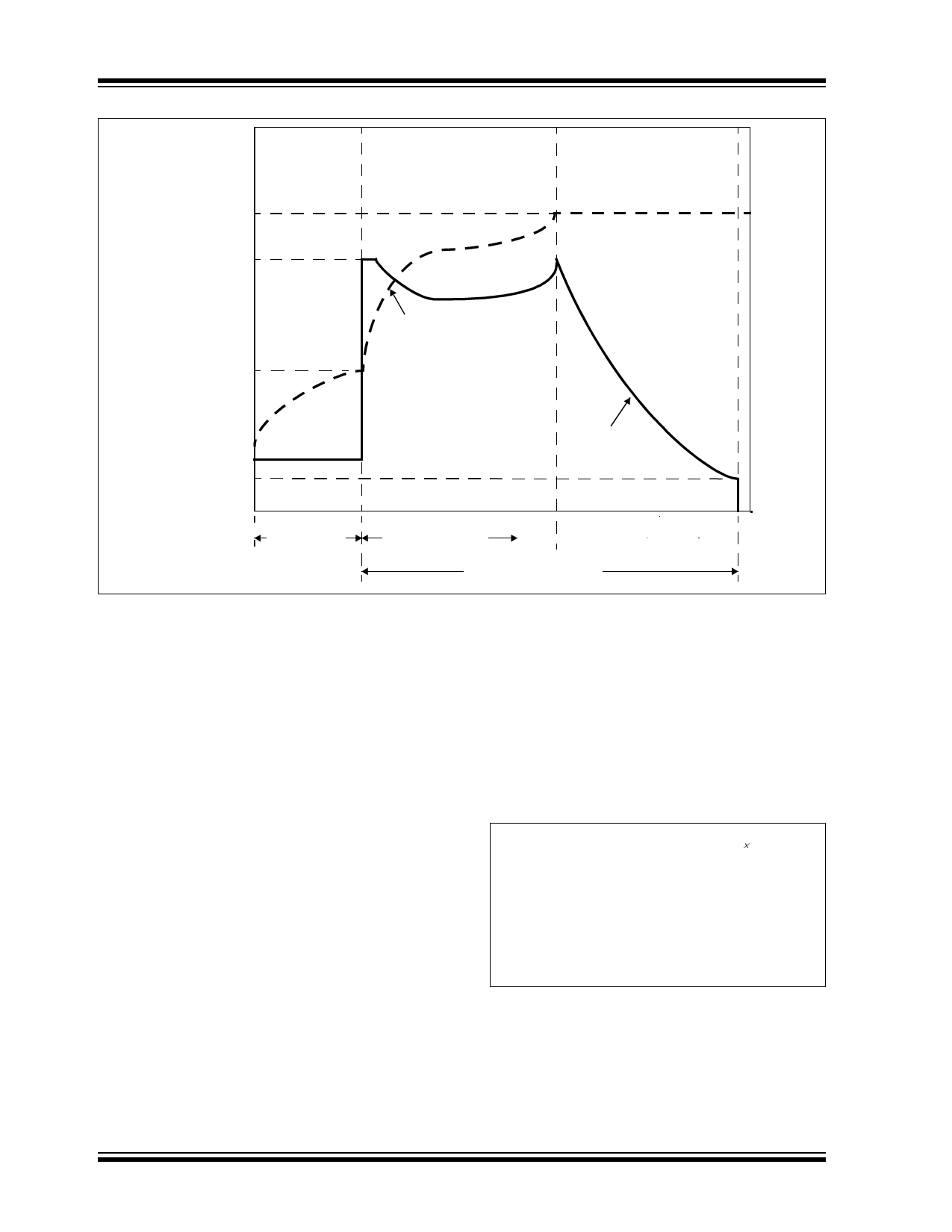
MCP73861/2/3/4
Preconditioning
Mode
Regulation
Voltage
(VREG)
Regulation
Current
(IREG)
Constant-Current
Mode
Constant-Voltage
Mode
Transition
Threshold
(VPTH)
Charge
Voltage
Precondition
Current
(IPREG)
Termination
Current
(ITERM)
Precondition
Safety Timer
Charge
Current
Fast Charge
Safety Timer
Elapsed Time
Termination Timer
FIGURE 6-3:
Typical Charge Profile in Thermal Regulation.
6.1 Application Circuit Design
Due to the low efficiency of linear charging, the most
important factors are thermal design and cost, which
are a direct function of the input voltage, output current
and thermal impedance between the battery charger
and the ambient cooling air. The worst-case situation is
when the device has transitioned from the
Preconditioning mode to the Constant-current mode. In
this situation, the battery charger has to dissipate the
maximum power. A trade-off must be made between
the charge current, cost and thermal requirements of
the charger.
6.1.1 COMPONENT SELECTION
Selection of the external components in Figure 6-1 is
crucial to the integrity and reliability of the charging
system. The following discussion is intended as a guide
for the component selection process.
6.1.1.1 Current Programming Resistor
(RPROG)
The preferred fast charge current for Lithium-Ion cells
is at the 1C rate, with an absolute maximum current at
the 2C rate. For example, a 500 mAh battery pack has
a preferred fast charge current of 500 mA. Charging at
this rate provides the shortest charge cycle times
without degradation to the battery pack performance or
life.
1200 mA is the maximum charge current obtainable
from the MCP7386X. For this situation, the PROG input
should be connected directly to VSS.
6.1.1.2 Thermal Considerations
The worst-case power dissipation in the battery
charger occurs when the input voltage is at the
maximum and the device has transitioned from the Pre-
conditioning mode to the Constant-current mode. In
this case, the power dissipation is:
PowerDissipation = VDDMAX – VPTHMIN IREGMAX
Where:
VDDMAX = the maximum input voltage
IREGMAX = the maximum fast charge current
VPTHMIN = the minimum transition threshold
voltage
DS21893F-page 20
2004-2013 Microchip Technology Inc.
Share Link: 