DHD2805SH 데이터 시트보기 (PDF) - M.S. Kennedy
부품명
상세내역
제조사
DHD2805SH Datasheet PDF : 7 Pages
| |||
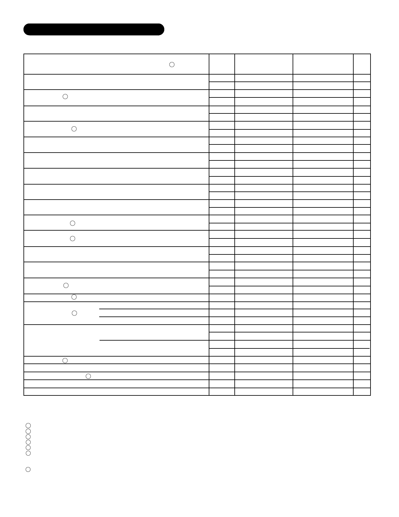
ELECTRICAL SPECIFICATIONS
Parameter
Output Voltage
Output Current 2
Output Voltage Ripple
Input Current Ripple 2
Line Regulation
Load Regulation
Efficiency
Step Load Response
Step Load Recovery
Step Line Response 2
Step Line Recovery 2
Start Up Overshoot
Start Up Delay
Shutdown Delay 2
Shutdown Recovery 2
Input Voltage Range 2
Quiescent Current
Capacitive Load 2
Isolation
Short Circuit Current Limit 7
Switching Frequency
VOUT Adjustment Range
Test Conditions 1
16V≤VIN≤40V
BW=10KHz to 2MHz
BW=10KHz to 2MHz
VIN=16V to 40V
VIN=28V
IOUT=120mA to/from 1500mA
IOUT=500mA to/from 1000mA
Transition TIme=30µS
IOUT=500mA to/from 1000mA
Transition TIme=30µS
VIN=16V to/from 40V
Transition Time=30µS, IOUT=1A
VIN=16V to/from 40V
Transition Time=30µS, IOUT=1A
IOUT=1A
IOUT=0A and 1A
POUT=7.5W MAX.
POUT=5W MAX.
POUT=2.5W MAX.
Enabled, IOUT=0mA
Disabled, IOUT=0mA
No Effect on DC Performance
Input to output or any pin to case @ 500V
RPOT=50KΩ
Group A
Subgroup
1
2,3
1
2,3
1
2,3
1
2,3
1
2,3
1
2,3
1
2,3
4
5,6
4
5,6
4
5,6
4
5,6
4
5,6
4
5,6
4
5,6
-
1,2,3
1,2,3
1,2,3
1
2,3
1
2,3
1,2,3
1
1
4
1
DHD2805S H/E
Min.
4.95
4.80
120
120
-
-
-
-
-
-
-
-
65
60
-
-
-
-
-
-
-
-
-
-
-
-
-
-
-
16
12
10
-
-
-
-
-
100
1.6
375
±10
Typ.
5.00
-
-
-
75
-
100
-
±9
-
±15
-
70
-
±300
-
90
-
±160
-
140
-
0
0
30
-
220
-
60
-
-
-
35
-
2
-
-
-
1.9
400
-
Max.
5.05
5.20
1500
1500
190
475
200
200
±25
±50
±35
±50
-
-
±500
±750
300
300
±500
±500
500
500
200
200
50
50
500
500
-
40
50
50
40
40
5
5
300
-
2.2
425
-
DHD2805S
Units
Min. Typ. Max.
4.90 5.00 5.10 VDC
-
-
-
VDC
120
-
1500 mA
-
-
-
mA
-
75
190 mVp-p
-
-
- mVp-p
-
100 225 mAp-p
-
-
- mAp-p
-
±9 ±30 mV
-
-
-
mV
-
±15 ±40 mV
-
-
-
mV
63
70
-
%
-
-
-
%
-
±300 ±500 mV
-
-
-
mV
-
90
300 µS
-
-
-
µS
-
±160 ±500 mV
-
-
-
mV
-
140 500 µS
-
-
-
µS
-
0
200 mV
-
-
-
mV
-
30
50
mS
-
-
-
mS
-
220 500 µS
-
-
-
µS
-
60
-
mS
16
-
40
V
12
-
50
V
10
-
50
V
-
35
45
mA
-
-
-
mA
-
2
5
mA
-
-
-
mA
-
-
300 µF
100
-
-
MΩ
1.5
1.9
2.3
A
350 400 450 KHz
±10
-
-
%
NOTES:
1 +VIN = 28V, IOUT = 1.5A, TA=TC=25°C unless otherwise specified.
2 Guaranteed by design but not tested. Typical parameters are representative of actual device performance but are for reference only.
3 Industrial grade and "E" suffix devices shall be tested to subgroups 1 and 4 unless otherwise specified.
4 Military grade devices ("H" suffix) shall be 100% tested to subgroups 1, 2, 3 and 4.
5 Subgroups 5 and 6 testing available upon request.
6 Subgroup 1, 4 TA=TC=+25°C
2, 5 TA=TC=+125°C
3, 6 TA=TC= -55°C
7 Device has internal shutdown feature that pulses the output with a low duty cycle during faults.
3
Rev. C 3/05
Share Link: 