M54HC423A 데이터 시트보기 (PDF) - STMicroelectronics
부품명
상세내역
제조사
M54HC423A Datasheet PDF : 14 Pages
| |||
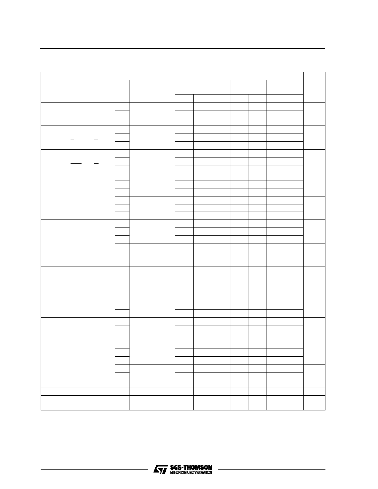
M54/M74HC423/423A
AC ELECTRICAL CHARACTERISTICS (CL = 50 pF, Input tr = tf = 6 ns)
Symbol
Parameter
Test Conditions
VCC
(V)
TA = 25 oC
54HC and 74HC
Value
-40 to 85 oC -55 to 125 oC Unit
74HC
54HC
Min. Typ. Max. Min. Max. Min. Max.
tTLH Output Transition 2.0
tTHL Time
4.5
30 75
95
8
15
19
ns
6.0
7
13
16
tPLH Propagation
2.0
tPHL Delay Time
4.5
(A, B - Q, Q)
6.0
102 210
265
29 42
53
ns
22 36
45
tPLH Propagation
2.0
tPHL Delay Time
4.5
(CLR - Q, Q)
6.0
68 160
200
20 32
40
ns
16 27
34
tWOUT Output Pulse
2.0 CX = 100 pF
1.3
Width
4.5 RX = 10 KΩ
1.1
µs
(for HC423)
6.0
1
2.0 CX = 0.1 µF
4.8
4.5 RX = 100 KΩ
4.6
ms
6.0
4.5
tWOUT Output Pulse
2.0 CX = 100 pF
1.7
Width
4.5 RX = 10 KΩ
1.4
µs
(for HC423A)
6.0
1.3
2.0 CX = 0.1 µF
10
4.5 RX = 100 KΩ
9.5
ms
6.0
9.5
∆tWOUT Output Pulse
±1
Width Error
Between Circuits
%
in Same Package
tW(H) Minimum Pulse 2.0
tW(L) Width
4.5
75
95
15
19
ns
6.0
13
16
tW(L) Minimum Pulse
2.0
Width
4.5
75
95
15
19
ns
6.0
13
16
trr
Minimum
2.0 CX = 100 pF
325
Retrigger Time
4.5
RX = 1 KΩ
108
ns
6.0
78
2.0 CX = 0.1 µF
5
4.5 RX = 100 KΩ
1.4
µs
6.0
1.2
CIN Input Capacitance
5
10
10
10 pF
CPD (*) Power Dissipation
160
Capacitance
pF
(*) CPD is defined as the value of the IC’s internal equivalent capacitance which is calculated from the operating current consumption without load.
(RefertoTestCircuit). Average operting current canbeobtained by the following equation. ICC(opr) =CPD •VCC •fIN +ICC’ Duty/100 + IC/2 (per monostable)
(ICC’: Active Supply Current) (Duty:%)
7/14
Share Link: 