LTC4065TRPBF 데이터 시트보기 (PDF) - Linear Technology
부품명
상세내역
제조사
LTC4065TRPBF Datasheet PDF : 16 Pages
| |||
LTC4065/LTC4065A
APPLICATIO S I FOR ATIO
Undervoltage Charge Current Limiting (UVCL)
The LTC4065/LTC4065A includes undervoltage charge
(∆VUVCL1) current limiting that prevents full charge cur-
rent until the input supply voltage reaches approximately
200mV above the battery voltage. This feature is particu-
larly useful if the LTC4065 is powered from a supply with
long leads (or any relatively high output impedance).
For example, USB-powered systems tend to have highly
variable source impedances (due primarily to cable quality
and length). A transient load combined with such imped-
ance can easily trip the UVLO threshold and turn the
charger off unless undervoltage charge current limiting is
implemented.
Consider a situation where the LTC4065 is operating
under normal conditions and the input supply voltage
begins to droop (e.g., an external load drags the input
supply down). If the input voltage reaches VBAT + ∆VUVCL1
(approximately 220mV above the battery voltage),
undervoltage charge current limiting will begin to reduce
the charge current in an attempt to maintain ∆VUVCL1
between the VCC input and the BAT output of the IC. The
LTC4065 will continue to operate at the reduced charge
current until the input supply voltage is increased or
voltage mode reduces the charge current further.
Operation from Current Limited Wall Adapter
By using a current limited wall adapter as the input
supply, the LTC4065 dissipates significantly less power
when programmed for a current higher than the limit of
the supply as compared to using a non-current limited
supply at the same charge current.
Consider a situation where an application demands a
600mA charge current for an 800mAh Li-Ion battery. If a
typical 5V (non-current limited) input supply is available
then the peak power dissipation inside the part can
exceed 1W.
Now consider the same scenario, but with a 5V input
supply with a 600mA current limit. To take advantage of
the supply, it is necessary to program the LTC4065 to
charge at a current above 600mA. Assume that the LTC4065
is programmed for 650mA (i.e., RPROG = 1.54k) to ensure
that part tolerances maintain a programmed current higher
than 600mA. Since the LTC4065 will demand a charge
current higher than the current limit of the voltage supply,
the supply voltage will drop to the battery voltage plus
600mA times the “on” resistance of the internal PFET. The
“on” resistance of the LTC4065 power device is approxi-
mately 450mΩ with a 5V supply. The actual “on” resis-
tance will be slightly higher due to the fact that the input
supply will drop to less than 5V. The power dissipated
during this phase of charging is less than 240mW. That is
a 76% improvement over the non-current limited supply
power dissipation.
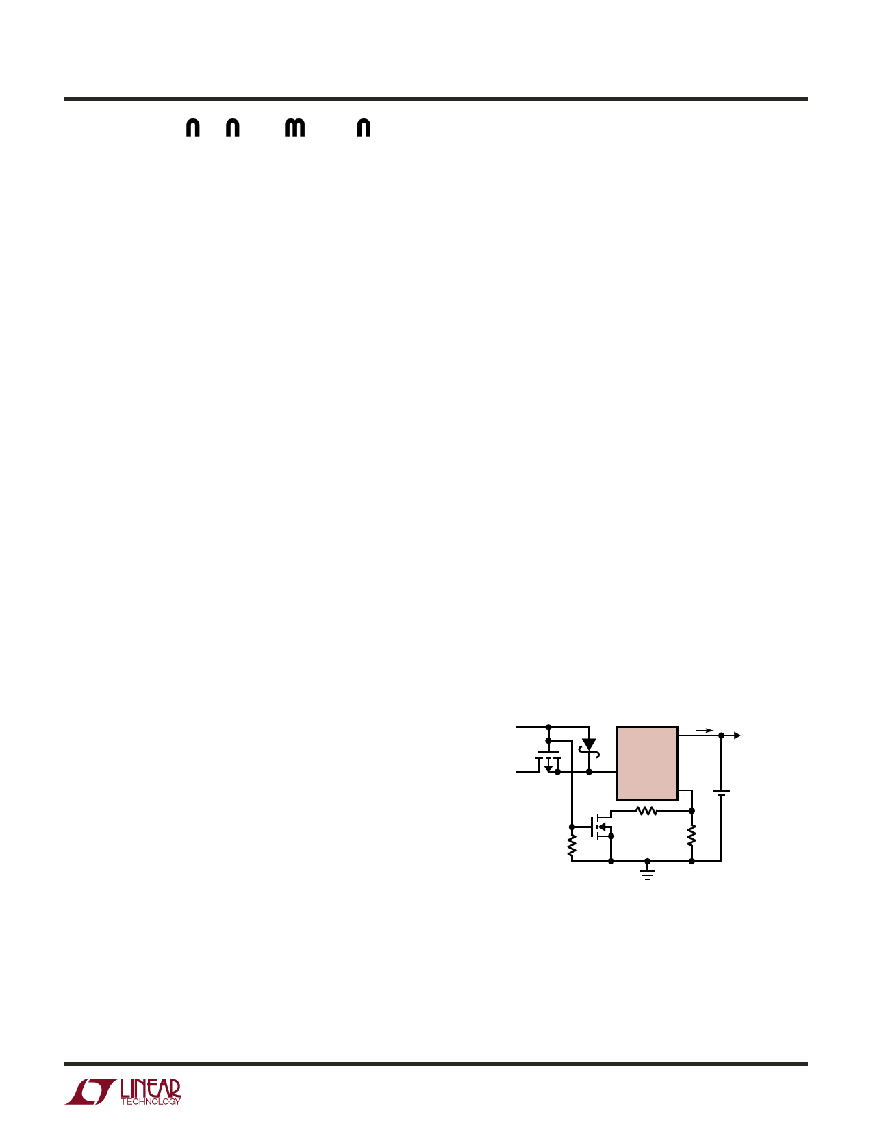
USB and Wall Adapter Power
Although the LTC4065/LTC4065A allow charging from a
USB port, a wall adapter can also be used to charge Li-Ion
batteries. Figure 3 shows an example of how to combine
wall adapter and USB power inputs. A P-channel MOSFET,
MP1, is used to prevent back conducting into the USB port
when a wall adapter is present and Schottky diode, D1, is
used to prevent USB power loss through the 1k pull-down
resistor.
Typically a wall adapter can supply significantly more
current than the 500mA-limited USB port. Therefore, an
N-channel MOSFET, MN1, and an extra program resistor
are used to increase the charge current to 750mA when the
wall adapter is present.
5V WALL
ADAPTER
750mA
ICHG
USB
POWER
500mA
ICHG
3 ICHG
BAT
SYSTEM
LOAD
LTC4065
4
VCC
MP1
6
PROG
+ Li-Ion
BATTERY
MN1 4.02k
1k
2k
4065 F03
Figure 3. Combining Wall Adapter and USB Power
Stability Considerations
The LTC4065/LTC4065A contain two control loops: con-
stant-voltage and constant-current. The constant-voltage
loop is stable without any compensation when a battery is
connected with low impedance leads. Excessive lead
4065f
13
Share Link: 