DS1243Y 데이터 시트보기 (PDF) - Dallas Semiconductor -> Maxim Integrated
부품명
상세내역
제조사
DS1243Y Datasheet PDF : 13 Pages
| |||
DS1243Y
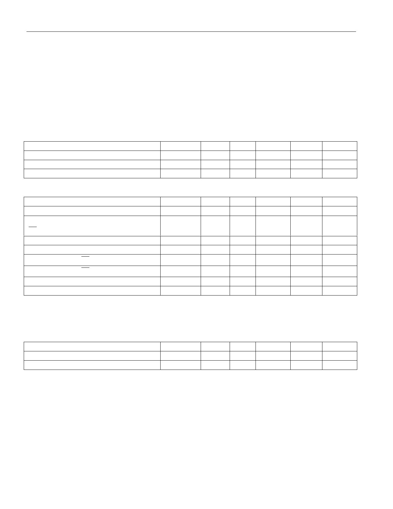
ABSOLUTE MAXIMUM RATINGS*
Voltage on Any Pin Relative to Ground
Operating Temperature
Storage Temperature
Soldering Temperature
–0.3V to +7.0V
0°C to 70°C
–40°C to +70°C
260°C for 10 seconds (See Note 13)
* This is a stress rating only and functional operation of the device at these or any other conditions
above those indicated in the operation sections of this specification is not implied. Exposure to
absolute maximum rating conditions for extended periods of time may affect reliability.
RECOMMENDED DC OPERATING CONDITIONS
PARAMETER
SYMBOL MIN TYP
Power Supply Voltage
Input Logic 1
Input Logic 0
VCC
4.5 5.0
VIH
2.2
VIL
-0.3
MAX
5.5
VCC+0.3
0.8
(0°C to 70°C)
UNITS NOTES
V
V
V
DC ELECTRICAL CHARACTERISTICS
PARAMETER
SYMBOL
Input Leakage Current
IIL
I/O Leakage Current
IIO
CE ≥ VIH ≤VCC
Output Current @ 2.4V
Output Current @ 0.4V
Standby Current CE = 2.2
IOH
IOL
ICCS1
Standby Current CE = VCC – 0.5V
Operating Current tCYC = 200ns
Write Protection Voltage
ICCS2
ICC01
VTP
MIN
-1.0
-1.0
-1.0
2.0
4.25
(0°C to 70°C; VCC = 5V ± 10%)
TYP MAX UNITS NOTES
+1.0
µA
12
+1.0
µA
mA
mA
5.0
10
mA
3.0
5.0
mA
85
mA
4.5
V
DC TEST CONDITIONS
Outputs are open; all voltages are referenced to ground.
CAPACITANCE
PARAMETER
Input Capacitance
Input/Output Capacitance
SYMBOL
CIN
CI/O
MIN
TYP
5
5
MAX
10
10
(tA = 25°C)
UNITS NOTES
pF
pF
6 of 13
Share Link: 