BYV72EW-200 데이터 시트보기 (PDF) - Philips Electronics
부품명
상세내역
제조사
BYV72EW-200 Datasheet PDF : 6 Pages
| |||
Philips Semiconductors
Rectifier diodes
ultrafast, rugged
Product specification
BYV72EW series
I
F
dI
F
dt
t
rr
time
Q
s
I
R
I
rrm
10% 100%
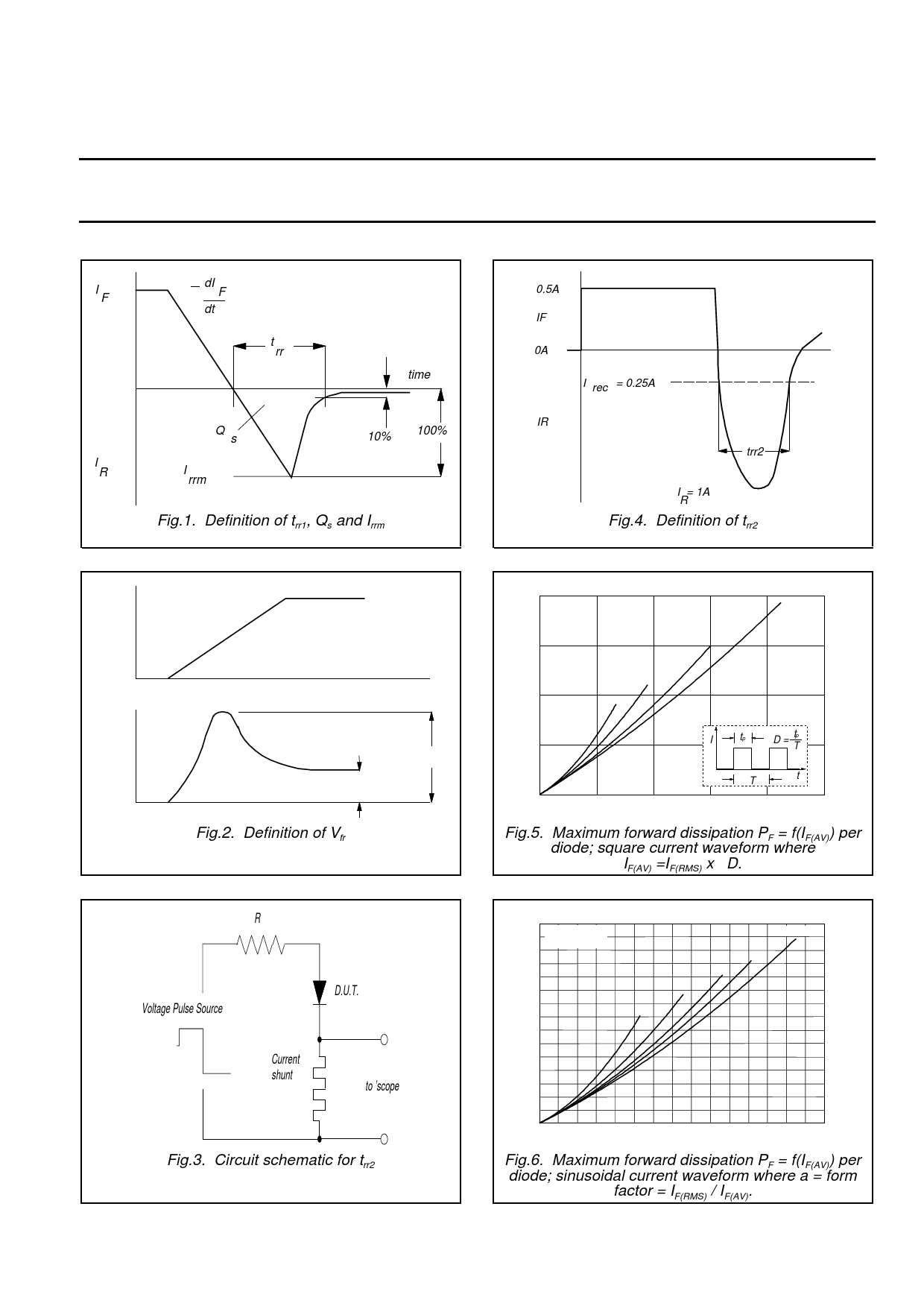
Fig.1. Definition of trr1, Qs and Irrm
0.5A
IF
0A
I rec = 0.25A
IR
trr2
I = 1A
R
Fig.4. Definition of trr2
IF
time
VF
VF
Fig.2. Definition of Vfr
V fr
time
R
Voltage Pulse Source
D.U.T.
Current
shunt
to ’scope
Fig.3. Circuit schematic for trr2
PF / W
20
Vo = 0.705 V
Rs = 0.0097 Ohms
15
10
0.1
BYV42
0.5
0.2
Tmb(max) / C
102
D = 1.0
114
126
5
I
tp
D
=
tp
T
138
T
t
0
150
0
5
10
15
20
25
IF(AV) / A
Fig.5. Maximum forward dissipation PF = f(IF(AV)) per
diode; square current waveform where
IF(AV) =IF(RMS) x √D.
PF / W
15
Vo = 0.705 V
Rs = 0.0097 Ohms
10
BYV42
2.2
2.8
4
Tmb(max) / C
114
a = 1.57
1.9
126
5
138
0
150
0
5
10
15
IF(AV) / A
Fig.6. Maximum forward dissipation PF = f(IF(AV)) per
diode; sinusoidal current waveform where a = form
factor = IF(RMS) / IF(AV).
October 1998
3
Rev 1.200
Share Link: 