KA3S0680 데이터 시트보기 (PDF) - Fairchild Semiconductor
부품명
상세내역
제조사
KA3S0680 Datasheet PDF : 12 Pages
| |||
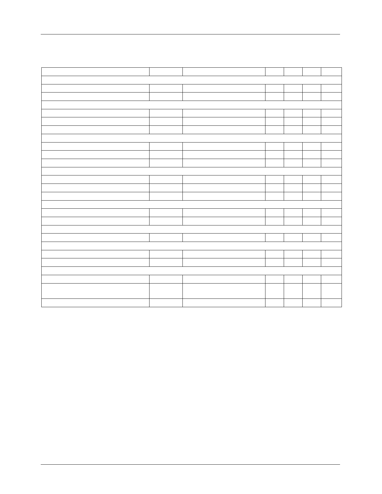
KA3S0680RB/KA3S0680RFB
Electrical Charcteristics (SFET part) (Continued)
(Ta = 25°C unless otherwise specified)
Characteristic
Symbol
UVLO SECTION
Start threshold voltage
VSTART
Stop operating voltage
VSTOP
OSCILLATOR SECTION
Initial accuracy
Frequency change with temperature (2)
FOSC
∆F/∆T
Maximum duty cycle
DMAX
FEEDBACK SECTION
Feedback source current
IFB
Shutdown Feedback voltage
VSD
Shutdown delay current
Idelay
SYNC. & SOFT START SECTION
Soft start voltage
VSS
Soft start current
Sync threshold voltage(3)
ISS
VSYTH
REFERENCE SECTION
Output voltage (1)
Temperature Stability (1)(2)
Vref
Vref/∆T
CURRENT LIMIT (SELF-PROTECTION) SECTION
Peak Current Limit
IOVER
PROTECTION SECTION
Thermal shutdown temperature (Tj) (1)
TSD
Over voltage protection voltage
VOVP
TOTAL DEVICE SECTION
Start Up current
ISTART
Operating supply current
(control part only)
IOP
VCC zener voltage
VZ
Test condition
-
After turn on
Ta = 25°C
−25°C ≤ Ta ≤ +85°C
-
Ta = 25°C, Vfb = GND
-
Ta = 25°C, 5V ≤ Vfb ≤VSD
VFB = 2V
Sync & S/S = GND
Vfb = 5V
Ta = 25°C
−25°C ≤ Ta ≤ +85°C
Max. inductor current
-
-
VCC = 14V
Ta = 25°C
ICC = 20mA
Min. Typ. Max. Unit
14 15 16 V
9 10 11 V
18 20 22 kHz
- ±5 ±10 %
92 95 98 %
0.7 0.9 1.1 mA
6.9 7.5 8.1 V
1.4 1.8 2.2 µA
4.7 5.0 5.3 V
0.8 1.0 1.2 mA
6.0 6.4 6.8 V
4.80 5.00 5.20 V
- 0.3 0.6 mV/°C
3.52 4.00 4.48 A
140 160 -
°C
23 25 28 V
0.1 0.3 0.55 mA
6 12 18 mA
30 32.5 35 V
Note:
1. These parameters, although guaranteed, are not 100% tested in production
2. These parameters, although guaranteed, are tested in EDS(water test) process
3.The amplitude of the sync. pulse is recommended to be between 2V and 3V for stable sync. function.
4
Share Link: 