DGT409BCA(2002) 데이터 시트보기 (PDF) - Dynex Semiconductor
부품명
상세내역
제조사
DGT409BCA Datasheet PDF : 11 Pages
| |||
DGT409BCA
9
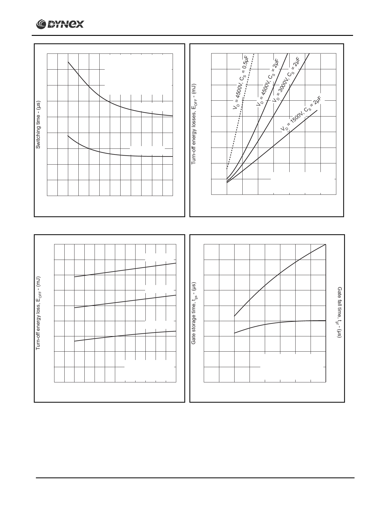
Conditions:
Tj = 115˚C, IT = 400A,
8
CS = 2µF, RS = 20Ω,
dIT/dt = 150A/µs,
7
dIFG/dt = 30A/µs,
VD = 3000V
6
Rise time -tr
5
4
3
Delay time -td
2
1
0
0
10
20
30
40
50
60
Peak forward gate current, IFGM - (A)
Fig.13 Switching times vs peak forward gate current
4500
4000
3500
3000
2500
2000
= 2µF
= 1500V, C S
VD
1500
1000
500
0
0
Conditions:
Tj = 115˚C,RS = 20Ω,
dIGG/dt = 20A/µs, CS = 2µF
200 400 600 800 1000 1200 1400 1600
On-state current, IT - (A)
Fig.14 Maximum turn-off energy vs on-state current
4500
4000
18
VD = 4500V
16
4.5
tgs
4.0
3500
14
3.5
3000
VD = 3000V
12
3.0
2500
2000
1500
10
VD = 1500V
8
6
2.5
tgf
2.0
1.5
1000
Conditions:
500
Tj = 115˚C, RS = 10Ω,
IT = 800A, CS = 2µF
0
0
10
20
30
40
50
60
Rate of rise of reverse gate current, dIGQ/dt - (A/µs)
Fig.15 Turn-off energy vs rate of rise of reverse
gate current
4
1.0
Conditions:
2
Tj = 115˚C, CS = 2µF,
RS = 20Ω, dIGQ/dt = 20A/µs
0.5
VDM = 3000V
0
0
0 100 200 300 400 500 600 700 800
Rate of rise of reverse gate current, dIGQ/dt - (A/µs)
Fig.16 Gate storage time and fall time vs on-state current
8/11
Share Link: 