74VHC112 데이터 시트보기 (PDF) - Fairchild Semiconductor
부품명
상세내역
제조사
74VHC112 Datasheet PDF : 7 Pages
| |||
Truth Table
Inputs
Outputs
PR CLR CP J K Q Q
L
H
X XX H L
H
L
X XX L H
L
L
X XX H H
H
H
H
H
h
l
h
h
Q0
L
Q0
H
H
H
hl H
L
H
H
l
l
Q0 Q0
H (h) = HIGH Voltage Level
L (l) = LOW Voltage Level
X = Immaterial
= HIGH-to-LOW Clock Transition
Q0 (Q0) = Before HIGH-to-LOW Transition of Clock
Lower case letters indicate the state of the referenced input or output one setup time prior to the HIGH-to-LOW clock transition.
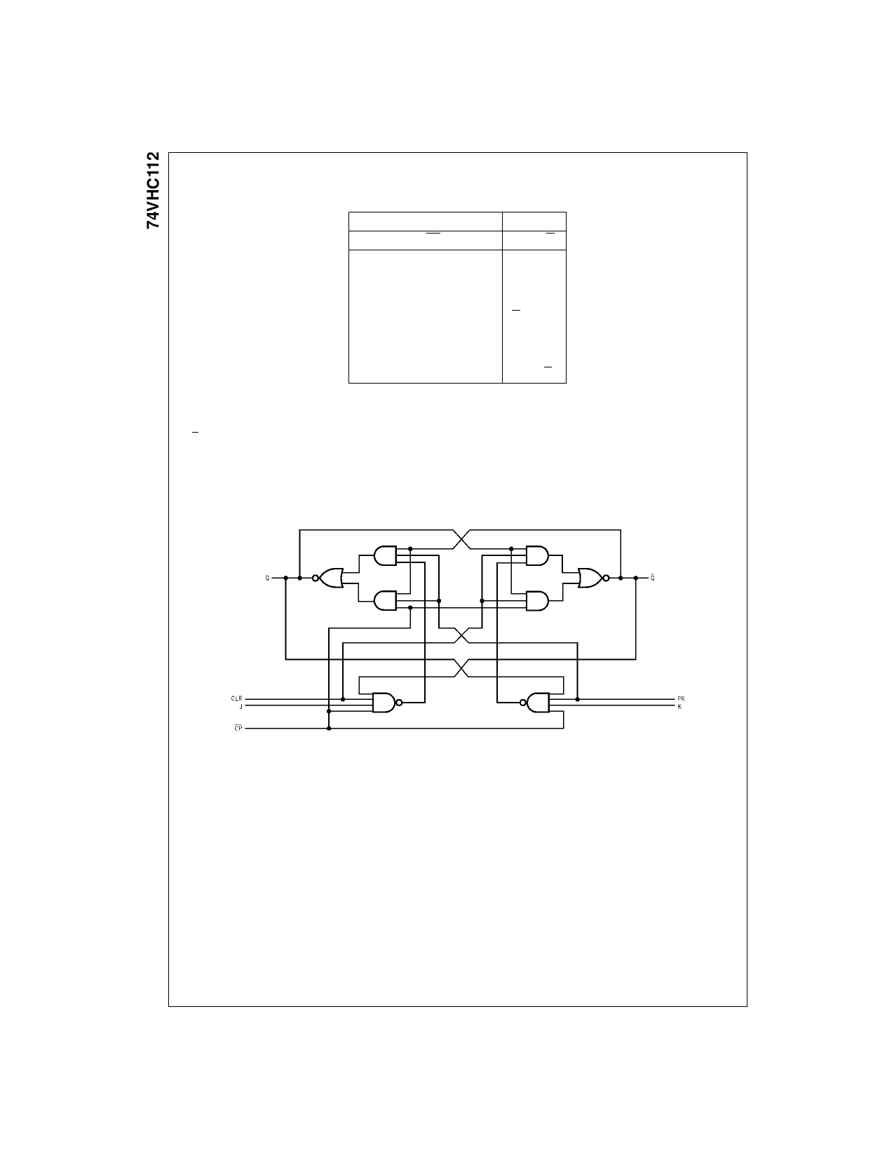
Logic Diagram
(One Half Shown)
www.fairchildsemi.com
2
Share Link: 