XRT8001ID(1999) 데이터 시트보기 (PDF) - Exar Corporation
부품명
상세내역
제조사
XRT8001ID Datasheet PDF : 36 Pages
| |||
Preliminary
XRT8001
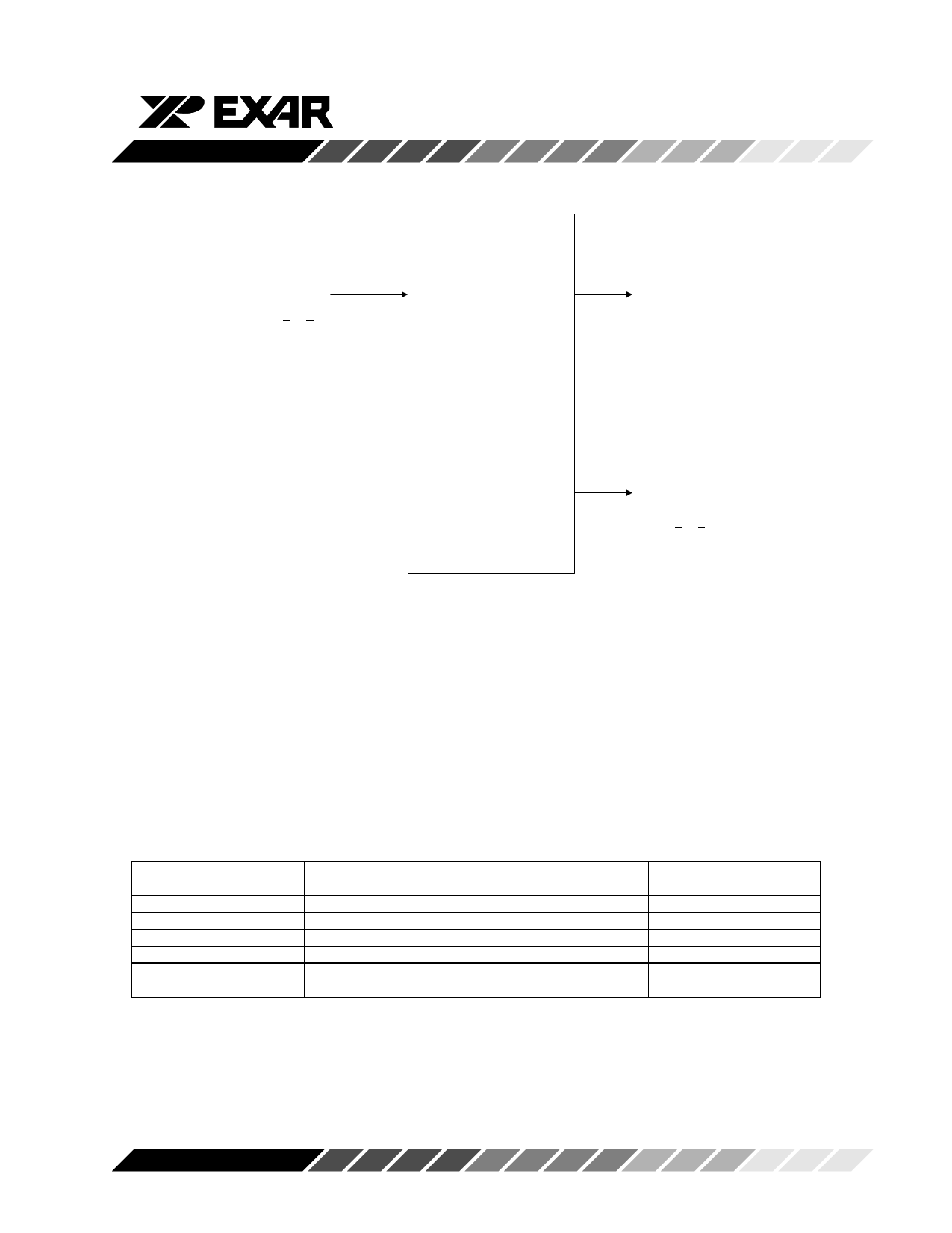
2.2 The “Reverse/Master” Mode
When the XRT8001 WAN Clock Device has been
configured to operate in the “Reverse/Master” Mode,
then it will accept either a “56kHz” or a “64kHz” clock
signal via the “Reference Clock” input at FIN (pin 3). In
response to this clock signal, the XRT8001 WAN
Clock Devicewill output either a “1.544MHz” or a
“2.048MHz” clock signal, via the Clock Output pins
(CLK1 and/or CLK2).
A simple illustration of the XRT8001 WAN Clock
device, operating in the “Reverse/Master” Mode is
presented in Figure 10.
56kHz
or
64kHz
FIN
CLK1
XXRRTT88000011
WWAANN CClloocckk
CLK2
1.544MHz
or
2.048MHz
1.544MHz
or
2.048MHz
Figure 10. Illustration of the XRT8001 WAN Clock
Device operating in the “Reverse/Master” Mode
Configuring the XRT8001 WAN Clock Device
into the “Reverse/Master” Mode
The user can configure the XRT8001 WAN Clock
Device to operate in the “Reverse/Master” Mode, by
executing the following steps:
Step 1 – Configure the XRT8001 Device to operate in
the “MASTER” Mode by pulling the “MSB” pin (pin 8)
to VDD.
Step 2 – Review Table 5, and determine which com-
bination of “Input Frequency” and “Output Frequen-
cies” (via PLL1 and PLL2) correlate with the desired
configuration.
Rev. P1.00
21
Share Link: 