74LX1G126CTR データシートの表示(PDF) - STMicroelectronics
部品番号
コンポーネント説明
メーカー
74LX1G126CTR Datasheet PDF : 12 Pages
| |||
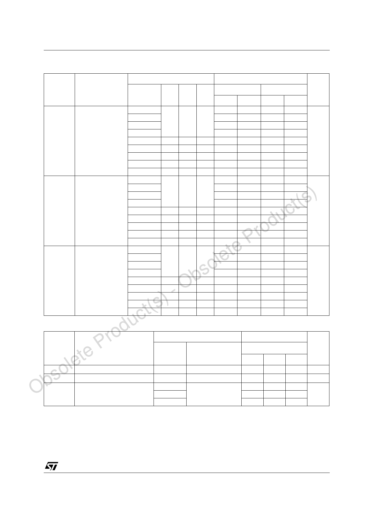
74LX1G126
AC ELECTRICAL CHARACTERISTICS (Input tr = tf = 3ns)
Test Condition
Value
Symbol
Parameter
VCC
CL RL ts = tr -40 to 85 °C
-55 to 125 °C Unit
(V)
(pF) (Ω) (ns) Min. Max. Min. Max.
tPLH tPHL Propagation Delay 1.65 to 1.95
2
12.0
2
12.0
Time
2.3 to 2.7
2
7.0
2
7.0
15 1MΩ 3.0
3.0 to 3.6
1
4.7
1
4.7
4.5 to 5.5
1
4.1
1
4.1
1.65 to 1.95 30 1000 2.0
2
8.0
2
8.0
ns
2.3 to 2.7 30 500 2.0
2
5.5
2
5.5
2.7
50 500 2.5
1
5.2
1
5.2
3.0 to 3.6 50 500 2.5
1
4.5
1
4.5
4.5 to 5.5 50 500 2.5
1
4.0
1
4.0
tPLZ tPHZ Output Disable Time 1.65 to 1.95
2
12.0
2
12.0
2.3 to 2.7
) 3.0 to 3.6
15 1MΩ 3.0
2
1
t(s 4.5 to 5.5
1
1.65 to 1.95 30 1000 2.0
2
uc 2.3 to 2.7 30 500 2.0
2
d 2.7
50 500 2.5
1
ro 3.0 to 3.6 50 500 2.5
1
P 4.5 to 5.5 50 500 2.5
1
te tPZL tPZH Output Enable Time 1.65 to 1.95
2
2.3 to 2.7
2
le 3.0 to 3.6 15 1MΩ 3.0
1
so 4.5 to 5.5
1
b 1.65 to 1.95 30 1000 2.0
2
O 2.3 to 2.7 30 500 2.0
2
- 2.7
50 500 2.5
1
) 3.0 to 3.6 50 500 2.5
1
t(s 4.5 to 5.5 50 500 2.5
1
uc CAPACITIVE CHARACTERISTICS
Prod Symbol
Parameter
lete CIN
soCOUT
ObCPD
Input Capacitance
Output Capacitance
Power Dissipation Capacitance
(note 1)
Test Condition
VCC
(V)
VIN = 0 or VCC
VIN = 0 or VCC
1.8
fIN = 10MHz
2.5
7.0
2
7.0
5.5
1
5.5
5.0
1
5.0
9.8
2
9.8
ns
6.0
2
6.0
5.7
1
5.7
5.5
1
5.5
4.2
1
4.2
12.0
2
12.0
7.0
2
7.0
6.0
1
6.0
5.5
1
5.5
9.4
2
9.4
ns
6.6
2
6.6
5.6
1
5.6
5.3
1
5.3
5.0
1
5.0
Value
TA = 25 °C
Unit
Min. Typ. Max.
4
pF
5
10
pF
18
18
pF
3.3
21
1) CPD is defined as the value of the IC’s internal equivalent capacitance which is calculated from the operating current consumption without
load. (Refer to Test Circuit). Average operating current can be obtained by the following equation. ICC(opr) = CPD x VCC x fIN + ICC
5/12
Share Link: 