S594TR データシートの表示(PDF) - Vishay Semiconductors
部品番号
コンポーネント説明
メーカー
S594TR Datasheet PDF : 10 Pages
| |||
S594T / S594TR / S594TRW
Vishay Semiconductors
20
0
-20
-40
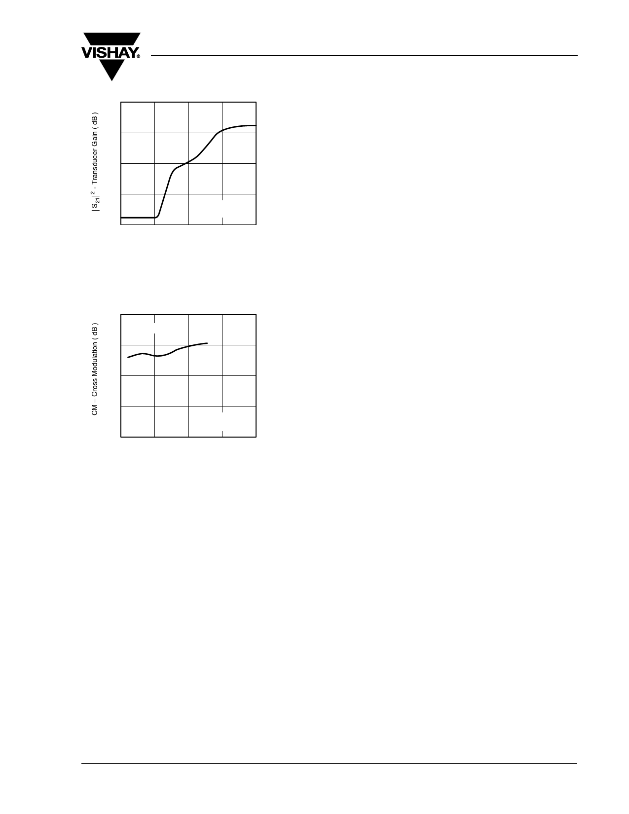
VDS = 5 V
f = 800 MHz
-60
0
1
2
3
4
95 10770
VG2S – Gate 2 Source Voltage ( V )
Figure 7. Transducer Gain vs. Gate 2 Source Voltage
80
Pin = -20 dBm
60
40
20
0
2
95 11144
VDS = 5 V
f = 800 MHz
3
4
5
6
VG2S – Gate 2 Source Voltage ( V )
Figure 8. Cross Modulation vs. Gate 2 Source Voltage
Document Number 85048
Rev. 1.6, 08-Sep-08
www.vishay.com
5
Share Link: 