UDA1351TS データシートの表示(PDF) - Philips Electronics
部品番号
コンポーネント説明
メーカー
UDA1351TS Datasheet PDF : 28 Pages
| |||
Philips Semiconductors
96 kHz IEC 958 audio DAC
Preliminary specification
UDA1351TS
8.5.2 L3 CONTROL MODE
The L3 control mode allows maximum flexibility in controlling the UDA1351TS.
It should be noted that, in the L3 control mode, several base-line functions are still controlled by pins on the device and
that, on start-up in the L3 control mode, the output is explicitly muted by bit MT via the L3 interface.
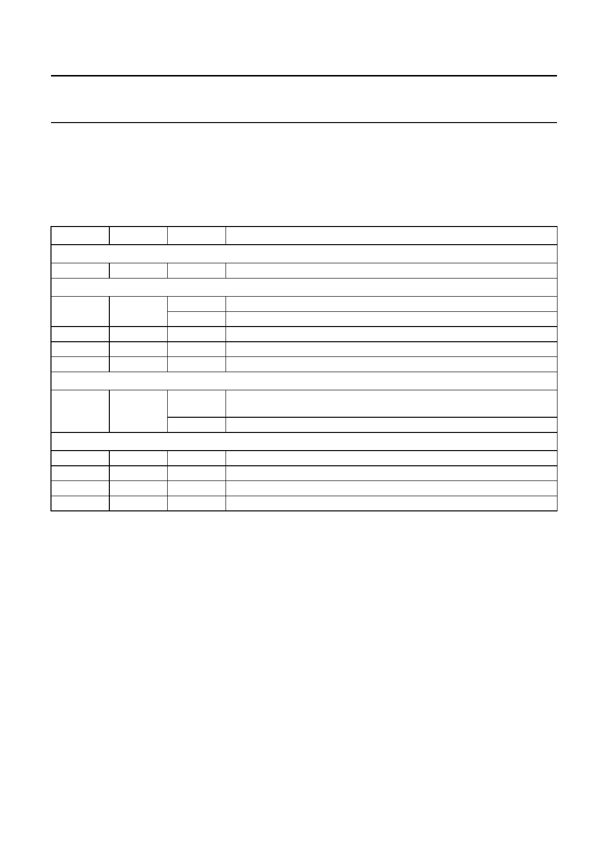
Table 4 Pin description in the L3 control mode
PIN
NAME
VALUE
FUNCTION
Mode selection pin
26
SELSTATIC
0
select L3 control mode; must be connected to VSSD
Input pins
5
RESET
0
normal operation
1
reset
8
L3DATA
9
L3CLOCK
10
L3MODE
−
must be connected to the L3-bus
−
must be connected to the L3-bus
−
must be connected to the L3-bus
Status pin
16
LOCK
0
clock regeneration and IEC 958 decoder out-of-lock or non-PCM data
detected
1
clock regeneration and IEC 958 decoder locked and PCM data detected
Test pins
4
TEST1
18
TEST2
25
TEST4
28
TEST3
0
must be connected to ground (VSSD)
0
must be connected to ground (VSSD)
1
must be connected to digital supply voltage (VDDD)
0
must be connected to ground (VSSD)
2000 Mar 28
11
Share Link: 