SI1142-A10-GMR データシートの表示(PDF) - Silicon Laboratories
部品番号
コンポーネント説明
メーカー
SI1142-A10-GMR Datasheet PDF : 76 Pages
| |||
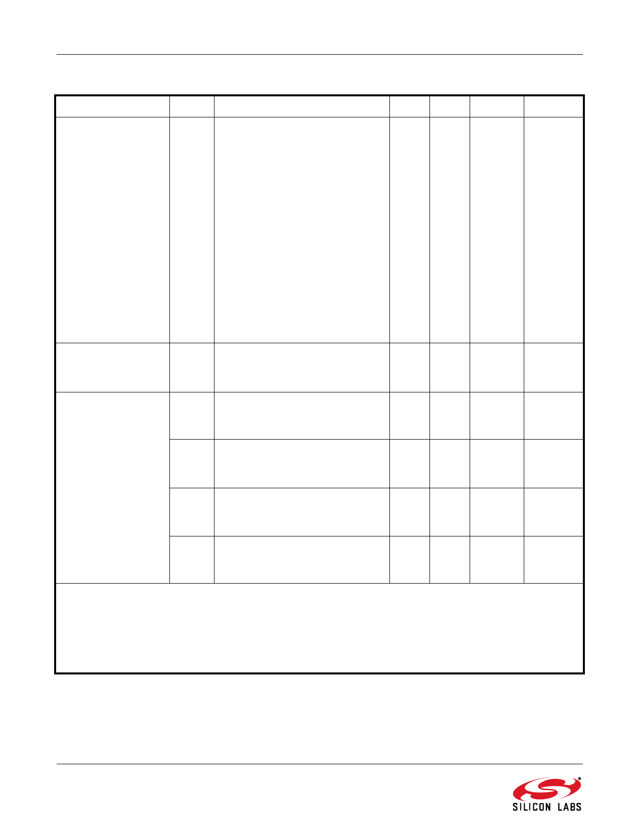
Si1141/42/43
Table 2. Performance Characteristics1 (Continued)
Parameter
Symbol
Condition
Min Typ
Max
Unit
LED1, LED2, LED3
ILEDx
VDD = 3.3 V, single drive
mA
Active Current
VLEDn = 1 V, PS_LEDn = 0001
3.5 5.6
7
VLEDn = 1 V, PS_LEDn = 0010
— 11.2
—
VLEDn = 1 V, PS_LEDn = 0011
13 22.4
29
VLEDn = 1 V, PS_LEDn = 0100
—
45
—
VLEDn = 1 V, PS_LEDn = 0101
—
67
—
VLEDn = 1 V, PS_LEDn = 0110
—
90
—
VLEDn = 1 V, PS_LEDn = 0111
— 112
—
VLEDn = 1 V, PS_LEDn = 1000
— 135
—
VLEDn = 1 V, PS_LEDn = 1001
— 157
—
VLEDn = 1 V, PS_LEDn = 1010
— 180
—
VLEDn = 1 V, PS_LEDn = 1011
— 202
—
VLEDn = 1 V, PS_LEDn = 1100
— 224
—
VLEDn = 1 V, PS_LEDn = 1101
— 269
—
VLEDn = 1 V, PS_LEDn = 1110
— 314
—
VLEDn = 1 V, PS_LEDn = 1111
— 359
—
Actively Measuring
Time4
Single PS
ALS VIS + ALS IR
Two ALS plus three PS
— 155
—
µs
— 285
—
µs
— 660
—
µs
Visible Photodiode
Response
Sunlight
ALS_VIS_ADC_GAIN = 0
VIS_RANGE = 0
— 0.282
—
ADC
counts/lux
2500K incandescent bulb
ALS_VIS_ADC_GAIN = 0
VIS_RANGE = 0
— 0.319
—
ADC
counts/lux
“Cool white” fluorescent
ALS_VIS_ADC_GAIN = 0
VIS_RANGE = 0
— 0.146
—
ADC
counts/lux
Infrared LED (875 nm)
ALS_VIS_ADC_GAIN = 0
VIS_RANGE = 0
— 8.277
—
ADC
counts.m2/
W
Notes:
1. Unless specifically stated in "Conditions", electrical data assumes ambient light levels < 1 klx.
2. Proximity-detection performance may be degraded, especially when there is high optical crosstalk, if the LED supply
and voltage drop allow the driver to saturate and current regulation is lost.
3. Guaranteed by design and characterization.
4. Represents the time during which the device is drawing a current equal to Iactive for power estimation purposes.
Assumes default settings.
6
Rev. 1.4
Share Link: 