TMC2011AN2C データシートの表示(PDF) - Cadeka Microcircuits LLC.
部品番号
コンポーネント説明
メーカー
TMC2011AN2C Datasheet PDF : 12 Pages
| |||
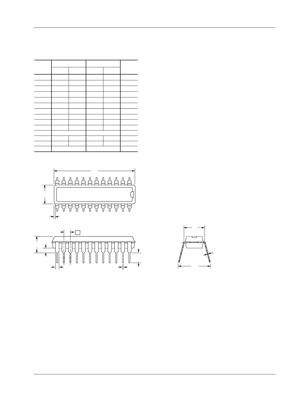
TMC2011A/2111A
Mechanical Dimensions (continued)
24-Lead Plastic DIP Package
Symbol
A
A1
A2
B
B1
C
D
D1
E
E1
e
eB
L
N
Inches
Min. Max.
—
.210
.015
—
.115 .195
.014 .022
.045 .070
.008 .015
1.125
.005
1.275
—
.300 .325
.240 .280
.100 BSC
—
.430
.115 .160
24
Millimeters
Min. Max.
—
5.33
.38
—
2.53 4.95
.36
.56
1.14 1.78
.20
.38
28.58
.13
32.39
—
7.62 8.26
6.10 7.11
2.54 BSC
—
10.92
2.92 4.06
24
Notes
4
2
2
5
PRODUCT SPECIFICATION
Notes:
1. Dimensioning and tolerancing per ANSI Y14.5M-1982.
2. "D" and "E1" do not include mold flashing. Mold flash or protrusions
shall not exceed .010 inch (0.25mm).
3. Terminal numbers are shown for reference only.
4. "C" dimension does not include solder finish thickness.
5. Symbol "N" is the maximum number of terminals.
D
12
E1
13
D1
e
A
A1
B1
1
24
L
B
E
C
eB
10
Share Link: 