XWM8739LEFL データシートの表示(PDF) - Wolfson Microelectronics plc
部品番号
コンポーネント説明
メーカー
XWM8739LEFL Datasheet PDF : 35 Pages
| |||
WM8739 / WM8739L
Advanced Information
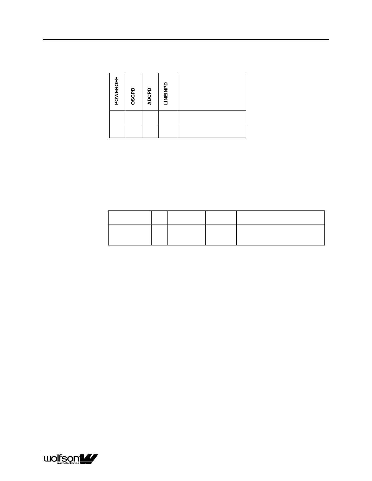
The device can be powered off by writing to the POWEROFF bit of the Power Down register. In
POWEROFF mode the Control Interface and a small portion of the digital remain active. The
analogue VMID reference is disabled. As in STANDBY mode the crystal oscillator pin can be
independently controlled. Refer to Table 18.
DESCRIPTION
1
0
X
X
1
1
X
X
Table 18 Power Off Mode
POWEROFF, but with Crystal
Oscillator OSC available
POWEROFF, Crystal
oscillator not-available
DEVICE RESETTING
The WM8739 contains a power on reset circuit that resets the internal state of the device to a known
condition. The power on reset is applied as DCVDD powers on and released only after the voltage
level of DCVDD crosses a minimum turn off threshold. If DCVDD later falls below a minimum turn on
threshold voltage then the power on reset is re-applied. The threshold voltages and associated
hysteresis are shown in the Electrical Characteristics table.
The user also has the ability to reset the device to a known state under software control as shown in
the table below.
REGISTER
ADDRESS
0001111
Reset Register
BIT
LABEL
8:0 RESET
Table 19 Software Control of Reset
DEFAULT
DESCRIPTION
not reset
Reset Register
Writing 00000000 to register resets
device
When using the software reset. In 3-wire mode the reset is applied on the rising edge of CSB and
released on the next rising edge of SCLK. In 2-wire mode the reset is applied for the duration of the
ACK signal (approximately 1 SCLK period, refer to Figure 20).
AI Rev 2.2 September 2001
26
Share Link: 