UPD16682AW データシートの表示(PDF) - NEC => Renesas Technology
部品番号
コンポーネント説明
メーカー
UPD16682AW Datasheet PDF : 55 Pages
| |||
µPD16682A
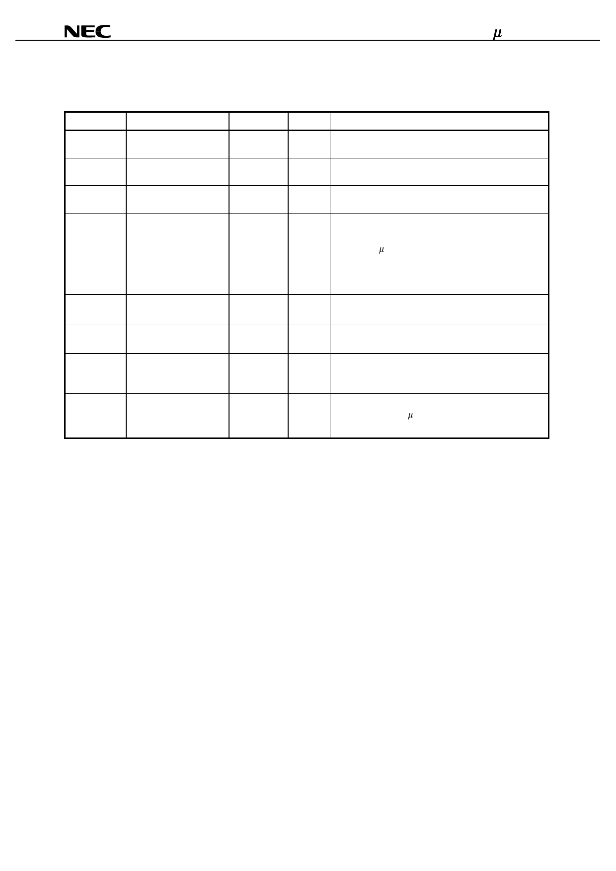
3. PIN FUNCTIONS
3.1 Power Supply System Pins
Pin Symbol
Pin Name
VDD
Logic power supply pins
VDD2
Booster circuit power
supply pins
VSS
Logic/driver ground pins
VLCD
Driver power supply pins
Pad No.
25 to 27
28 to 31
32 to 37
38 to 40
VDD’
VSS’
VLC1 to VLC5
C1+, C1−
C2+, C2−
C3+, C3−
Power supply pins for fixed 10,16,53,54,
mode pins
78,84,88
Ground pins for fixed
mode pins
7,13,57,58,
71,72,81,86
Reference power supply
pins for driver
59 to 68
Capacitor connection pins 41 to 52
I/O
Description
— Power supply pins for logic. Apply the logic power supply
voltage from an external source.
— Power supply pins for booster circuit. Apply the booster
circuit power supply voltage from an external source.
— Ground pins for logic and driver circuit. Connect these
pins to an external ground.
— Power supply pins for driver. Output pins for internal
booster circuit.
Connect a 1-µF capacitor for boosting between these pins
and the GND pins.
If not using the internal booster circuit, a direct driver
power supply can be input.
— These power supply pins are used to set the mode pins as
fixed.
— These ground pins are used to set the mode pins as fixed.
— These are reference power supply pins for the LCD driver.
Connect a smoothing capacitor if an internal bias has
been selected.
— These are capacitor connection pins for the booster
circuit. Connect a 1-µF capacitor.
Data Sheet S14402EJ1V0DS
7
Share Link: 