ST72754J9B1/XXX データシートの表示(PDF) - STMicroelectronics
部品番号
コンポーネント説明
メーカー
ST72754J9B1/XXX
STMicroelectronics
ST72754J9B1/XXX Datasheet PDF : 144 Pages
| |||
ST72774/ST727754/ST72734
PIN DESCRIPTION (Cont’d)
RESET: Bidirectional. This active low signal forces
the initialization of the MCU. This event is the top
priority non maskable interrupt. This pin is
switched low when the Watchdog has triggered or
VDD is low. It can be used to reset external
peripherals.
OSCIN/OSCOUT: Input/Output Oscillator pin.
These pins connect a parallel-resonant crystal, or
an external source to the on-chip oscillator.
TEST/VPP: Input. EPROM programming voltage.
This pin must be held low during normal operating
modes.
VDD: Power supply voltage (4.0V-5.5V)
VSS: Digital Ground.
Alternate Functions: several pins of the I/O ports
assume software programmable alternate
functions as shown in the pin description
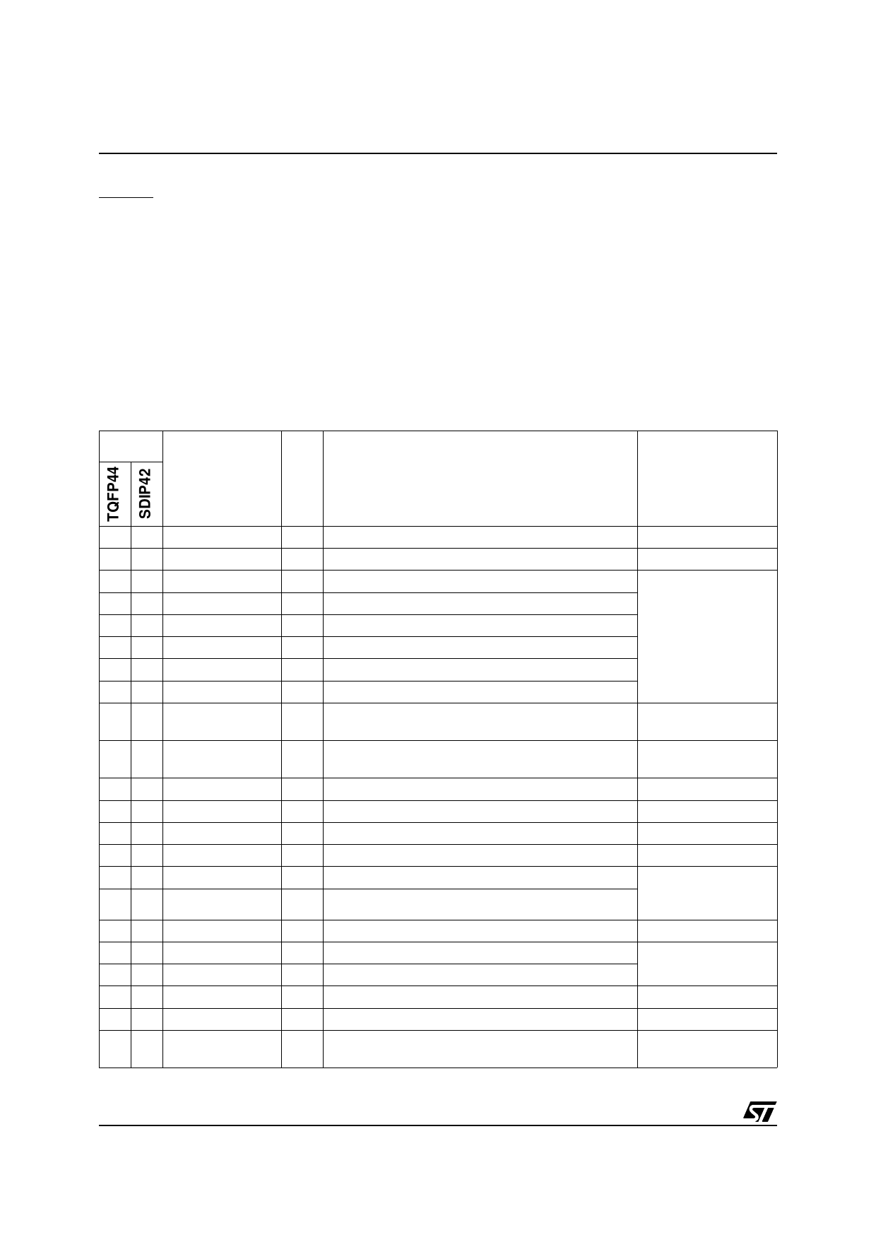
Table 1. ST727x4 Pin Description
Pin No.
Pin Name Type
Description
Remarks
39 1
40 2
41 3
42 4
43 5
44 6
17
28
39
PC0/HSYNCDIV
PC1/AV
PC2/PWM3
PC3/PWM4
PC4/PWM5
PC5/PWM6
PC6/PWM7
PC7/PWM8
PB7/AIN3/PWM2
4 10 PB6/AIN2/PWM1
5 11 PB5/AIN1
6 12 PB4/AIN0
8 13 VDD
9 14 USBVCC
10 15 USBDM
11 16 USBDP
12 17 VSS
13 18 HSYNCI
14 19 VSYNCI
15 20 PD0/VSYNCO
16 21 PD1/HSYNCO
17 22 PD2/CSYNCI
I/O Port C0 or HSYNCDIV output (HSYNCO divided by 2)
I/O Port C1 or “Active Video” input
I/O Port C2 or 10-bit PWM/BRM output 3
I/O Port C3 or 10-bit PWM/BRM output 4
I/O Port C4 or 10-bit PWM/BRM output5
I/O Port C5 or 10-bit PWM/BRM output 6
For analog controls,
after external filtering
I/O Port C6 or 10-bit PWM/BRM output 7
I/O Port C7 or 10-bit PWM/BRM output 8
I/O
Port B7 or ADC analog input 3 or 10-bit PWM/BRM
output 2
I/O
Port B6 or ADC analog input 2 or 10-bit PWM/BRM
output 1
I/O Port B5 or ADC analog input 1
I/O Port B4 or ADC analog input 0
S Supply (4.0V - 5.5V)
S USB power supply (output 3.3V +/- 10%)
I/O USB bidirectional data
I/O USB bidirectional data
Must be tied to ground
for devices without
USB peripheral
S Ground 0V
I SYNC horizontal synchronisation input
I SYNC vertical synchronisation input
TTL levels
Refer to Figure 16
I/O Port D0 or SYNC vertical synchronisation output
I/O Port D1 or SYNC horizontal synchronisation output
I/O Port D2 or SYNC composite synchronisation input
TTL levels with pull-up
(SYNC input)
8/144
3
Share Link: 