PQ025EZ01Z データシートの表示(PDF) - Sharp Electronics
部品番号
コンポーネント説明
メーカー
PQ025EZ01Z Datasheet PDF : 19 Pages
| |||
SHARP CORPORfiTION
7. Notes
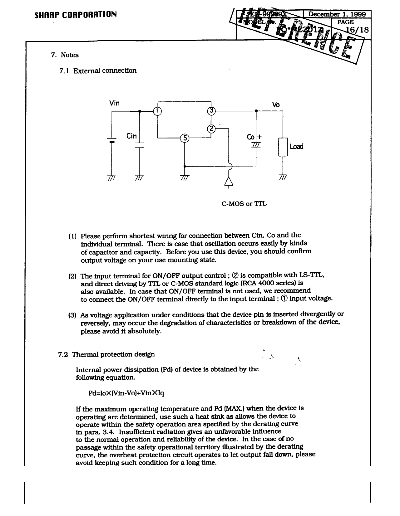
7.1 External connection
C-MOS or TIL
(1) Please perform shortest wiring for connection between Cm, Co and the
individual terminal. There is case that oscillation occurs easily by kinds
of capacitor and capacity. Before you use this device, you should confirm
output voltage on your use mounting state.
(2) The input terminal for ON/OFF output control ; @ is compatible with IS-‘ITI+
and direct driving by ‘ITL or C-MOS standard logic (RCA 4000 series) is
also available. In case that ON/OFF terminal is not used, we recommend
to connect the ON/OFF terminal dire&Q to the input terminal ; @ input voltage.
(3) As voltage application under conditions that the device pin is inserted divergently or
reversely, may occur the degradation of characteristics or breakdown of the device.
please avoid it absolutely.
7.2 Thermal protection design
I
(.
i\
Internal power dissipation (Pd) of device is obtained by the
following equation.
Pd=IoX(Vin-Vo)+VinXIq
If the maximum operating temperature and Pd (MAX.) when the device is
operating are determined. use such a heat sink as allows the device to
operate within the safety operation area specified by the derating curve
in para. 3.4. Insufhcient radiation gives an unfavorable infIuence
to the normal operation and reliabihty of the device. In the case of no
passage within the safety operational territory fflustrated by the derating
curve, the overheat protectton circuit operates to let output fall down, please
avoid keeping such condition for a long time.
Share Link: 