ML7012-04GA データシートの表示(PDF) - Oki Electric Industry
部品番号
コンポーネント説明
メーカー
ML7012-04GA Datasheet PDF : 22 Pages
| |||
1Semiconductor
FEDL 7012-04-01
ML7012-04
Analog Interface
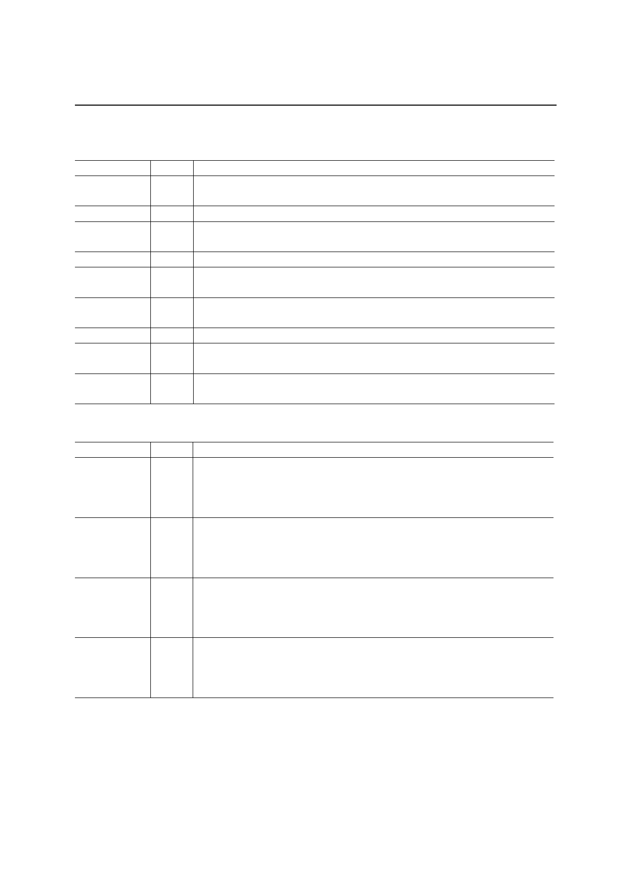
Symbol
AOUT
RCI
RCAO
TXAI
TXAN
TXAP
AIN
GSR
SG
I/O
Description
Transmit analog output pin
O
When PDN/RST = “0”, AOUT is in a high impedance state.
I Operational amplifier input pin constituting transmit RC active
Operational amplifier output pin constituting transmit RC active
O
When PDN/RST = “0”, RCAO is in a high impedance state.
I Input pin of the line transformer drive amplifier
Output pin of the line transformer drive amplifier (1)
O
When PDN/RST = “0”, TXAN is in a high impedance state.
Output pin of the line transformer drive amplifier (2)
O
When PDN/RST = “0”, TXAP is in a high impedance state.
I Input pin of the receive input amplifier
Output pin of the receive input amplifier
O
When PDN/RST = “0”, GSR is in a high impedance state.
Pin to connect capacitors for the SG circuit
O
When PDN/RST = “0”, SG is in a high impedance state.
PSTN Line Control Interface
Symbol
RLY1
RLY2
RII
SPK
I/O
Description
Off-hook and pulse dial control signal output pin (*1)
0: On-hook or break state of pulse dial
O
1: Off-hook or make state of pulse dial
When PDN/RST = “0”, RLY1 outputs “0”.
The control signal output pin to disconnect interlinked telephones (*1)
0: PSTN is connected with interlinked telephones
O
1: PSTN is disconnected with interlinked telephones but connected with modem
When PDN/RST = “0”, RLY2 outputs “0”.
Incoming signal input pin (*2)
Input “0” while detecting an incoming signal
I
Input “1” while not detecting an incoming signal
Fix this pin to "1" when a ring detector is not used.
Speaker control signal output pin
0: speaker On
O
1: speaker Off
When PDN/RST = “0”, SPK outputs “1”.
5/22
Share Link: 