MC88915FN55 データシートの表示(PDF) - Motorola => Freescale
部品番号
コンポーネント説明
メーカー
MC88915FN55 Datasheet PDF : 13 Pages
| |||
MC88915
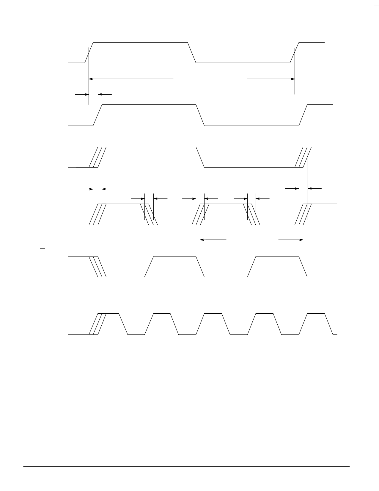
SYNC INPUT
(SYNC[1] or
SYNC[0])
t PD
FEEDBACK
INPUT
tCYCLE SYNC INPUT
Q/2 OUTPUT
tSKEWALL
Q0 – Q4
OUTPUTS
Q5 OUTPUT
tSKEWf
tSKEWr
tSKEWf
tCYCLE “Q” OUTPUTS
tSKEWR
2X_Q OUTPUT
Figure 4. Output / Input Switching Waveforms and Timing Diagrams
(These waveforms represent the hook–up configuration of Figure 5a on page 9)
Timing Notes:
• The MC88915 aligns rising edges of the FEEDBACK input and SYNC input, therefore the SYNC input does
not require a 50% duty cycle.
• All skew specs are measured between the VCC/2 crossing point of the appropriate output edges.All skews
are specified as ‘windows’, not as a ± deviation around a center point.
• If a “Q” output is connected to the FEEDBACK input (this situation is not shown), the “Q” output frequency
would match the SYNC input frequency, the 2X_Q output would run at twice the SYNC frequency, and the
Q/2 output would run at half the SYNC frequency.
MOTOROLA
8
TIMING SOLUTIONS
BR1333 — Rev 6
Share Link: 