MAPDCC0009 データシートの表示(PDF) - M/A-COM Technology Solutions, Inc.
部品番号
コンポーネント説明
メーカー
MAPDCC0009 Datasheet PDF : 5 Pages
| |||
MAPDCC0009
Low Cost Four-Way GMIC SMT Power Divider
824 – 960 MHz
Electrical Specifications: TA = +25°C, Z0 = 50
Parameter
Insertion Loss Above 6.0 dB
Isolation
VSWR Input
Output
Amplitude Balance
Phase Balance
Units
Min
dB
—
dB
20
—
—
—
—
dB
—
°
—
Rev. V2
Typ
0.8
24
1.4:1
1.25:1
0.3
3
Max
1.1
—
1.7:1
1.5:1
0.6
6
Absolute Maximum Ratings 2,3
Parameter
Input Power4
Operating Temperature
Storage Temperature
Absolute Maximum
1W CW
-40°C to +85°C
-65°C to +150°C
2. Exceeding any one or combination of these limits may cause
permanent damage to this device.
3. M/A-COM does not recommend sustained operation near
these survivability limits.
4. With internal load dissipation of 0.125 W maximum.
Handling Procedures
Please observe the following precautions to avoid
damage:
Static Sensitivity
GMIC Circuits are sensitive to electrostatic
discharge (ESD) and can be damaged by static
electricity. Proper ESD control techniques should
be used when handling these devices.
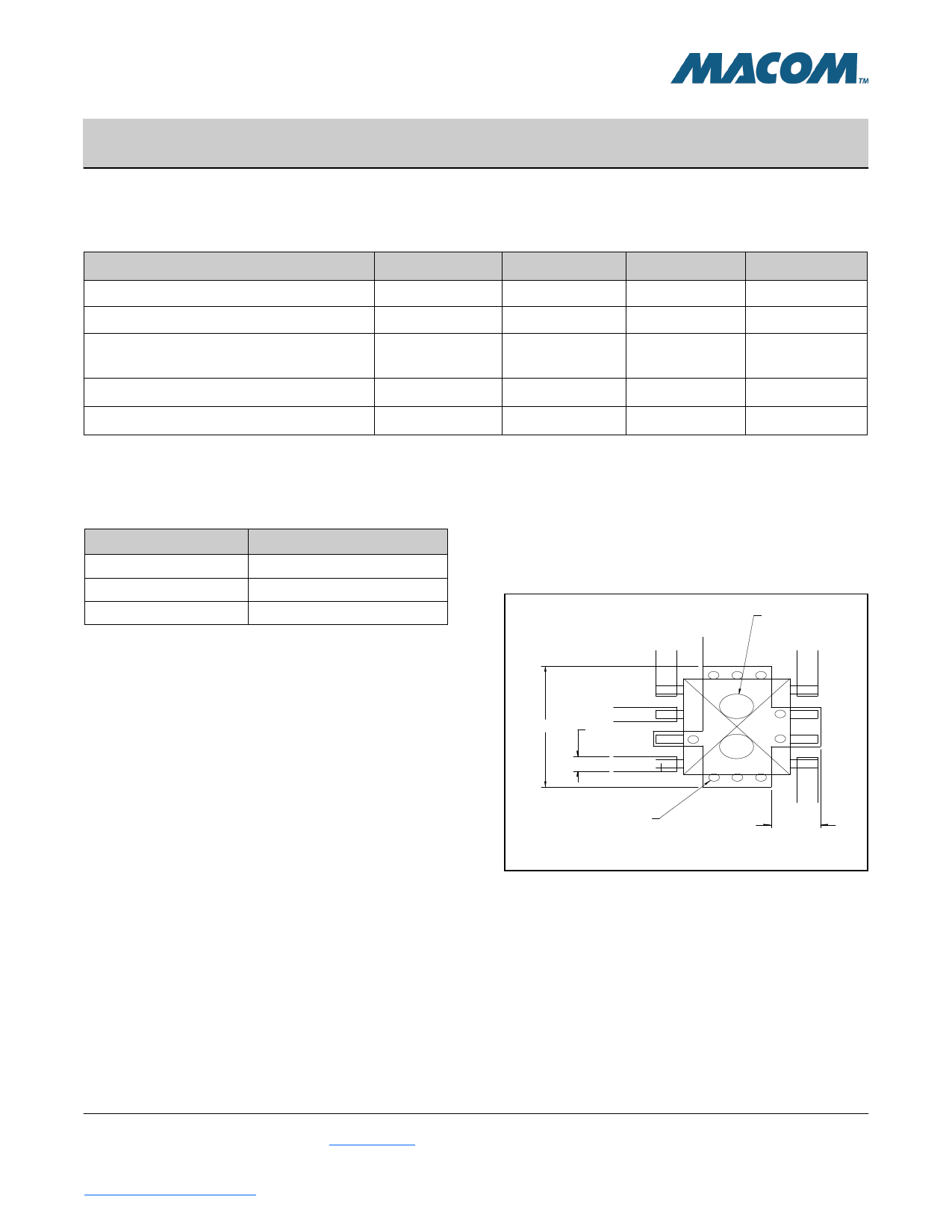
Recommended PCB Configuration
RF OUT .000
2X ° .050
PLATED THRU
RF OUT
RF IN
.244
.030 TYP.
RF OUT
12X ° .016
PLATED THRU
RF OUT
.072
2
M/A-COM Technology Solutions Inc. (MACOM) and its affiliates reserve the right to make changes to the product(s) or information contained herein without notice.
Visit www.macom.com for additional data sheets and product information.
For further information and support please visit:
https://www.macom.com/support
Share Link: 