LB1881V データシートの表示(PDF) - SANYO -> Panasonic
部品番号
コンポーネント説明
メーカー
LB1881V Datasheet PDF : 7 Pages
| |||
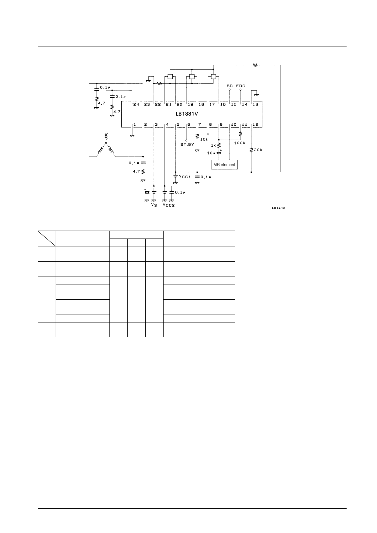
Sample Application Circuit
LB1881V
Logic Value Table
Source
Sink U
W phase → V phase
1
H
V phase → W phase
W phase → U phase
2
H
U phase → W phase
V phase → W phase
3
L
W phase → V phase
U phase → V phase
4
L
V phase → U phase
V phase → U phase
5
H
U phase → V phase
U phase → W phase
6
L
W phase → U phase
Input
V
W
H
L
L
L
L
H
H
L
L
H
H
H
Forward and reverse control
F/RC
L
H
L
H
L
H
L
H
L
H
L
H
Inputs:
High: For each phase, the input 1 potential is at least 0.2 V higher than the input 2 potential.
Low: For each phase, the input 1 potential is at least 0.2 V lower than the input 2 potential.
Forward/reverse control:
High: 2.8 V to VCC1
Low: 0 to 1.2 V
Units (resistance: Ω, capacitance: F)
No. 4456-6/7
Share Link: 