L6221N データシートの表示(PDF) - STMicroelectronics
部品番号
コンポーネント説明
メーカー
L6221N Datasheet PDF : 15 Pages
| |||
L6221AS - L6221AD - L6221N
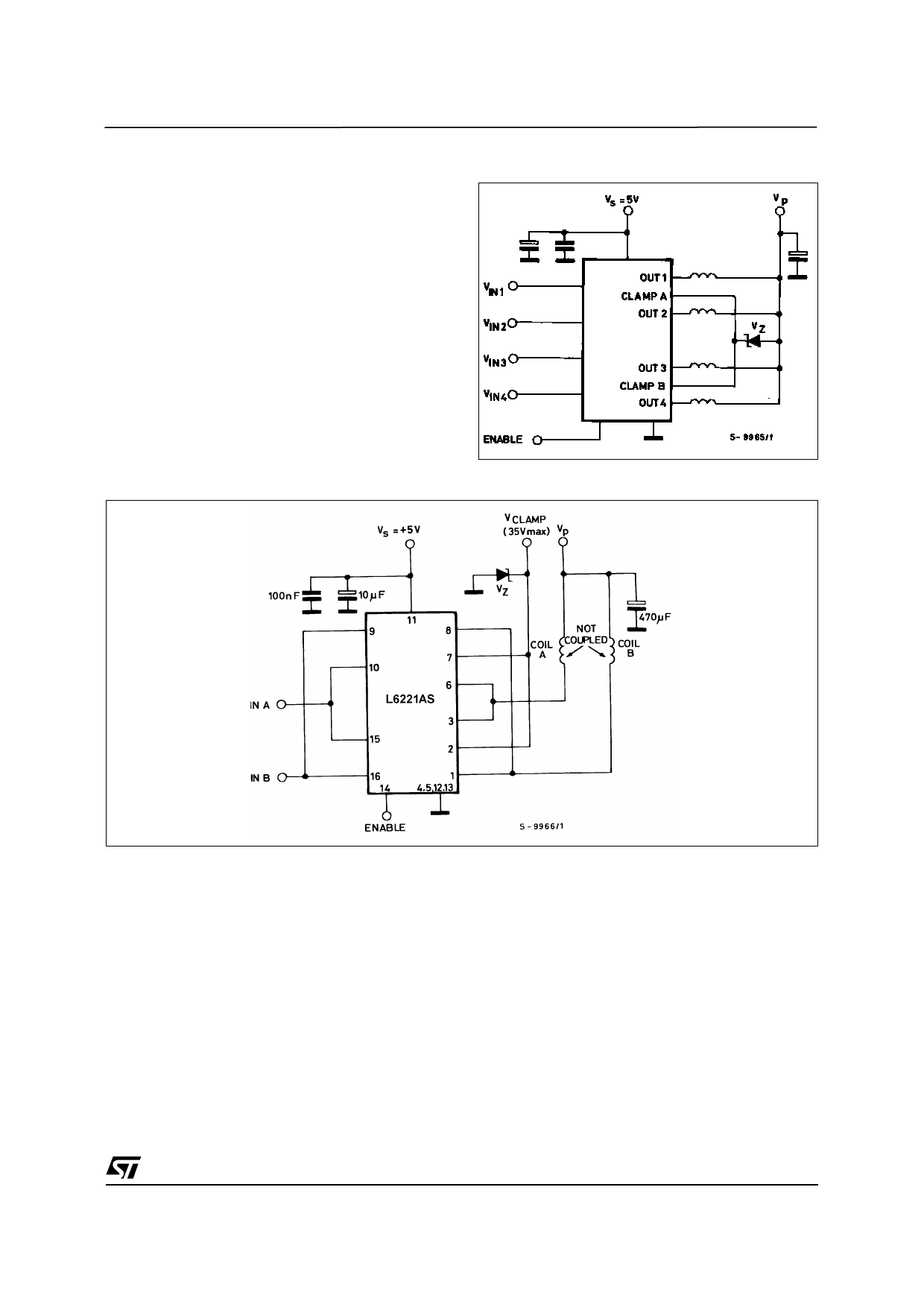
APPLICATION INFORMATION
When inductive loads are driven by L6221A/N, a
zener diode in series with the integral free-wheeling
diodes increases the voltage across which energy
stored in the load is discharged and therefore
speeds the current decay (fig. 18).
For reliability it is suggested that the zener is chosen
so that Vp + Vz < 35 V.
The reasons for this are two fold :
1) The zener voltage changes in temperature and
current.
2) The instantaneous power must be limited to avoid
the reverse second breakdown.
Figure 18.
Figure 19 : Driver for Solenoids up to 3A.
Some care must be taken to ensure that the collec-
tors are placed close together to avoid different cur-
rent partitioning at turn-off.
We suggest to put in parallel channel 1 and 4 and
channel 2 and 3 as shown in figure 19 for the similar
electrical characteristics of the logic section (turn-on
and turn-off delay time) and the power stages (col-
lector saturation voltage, free-wheeling diode for-
ward voltage).
9/15
Share Link: 