KA3016D データシートの表示(PDF) - Fairchild Semiconductor
部品番号
コンポーネント説明
メーカー
KA3016D Datasheet PDF : 18 Pages
| |||
CD-ROM PRODUCTS
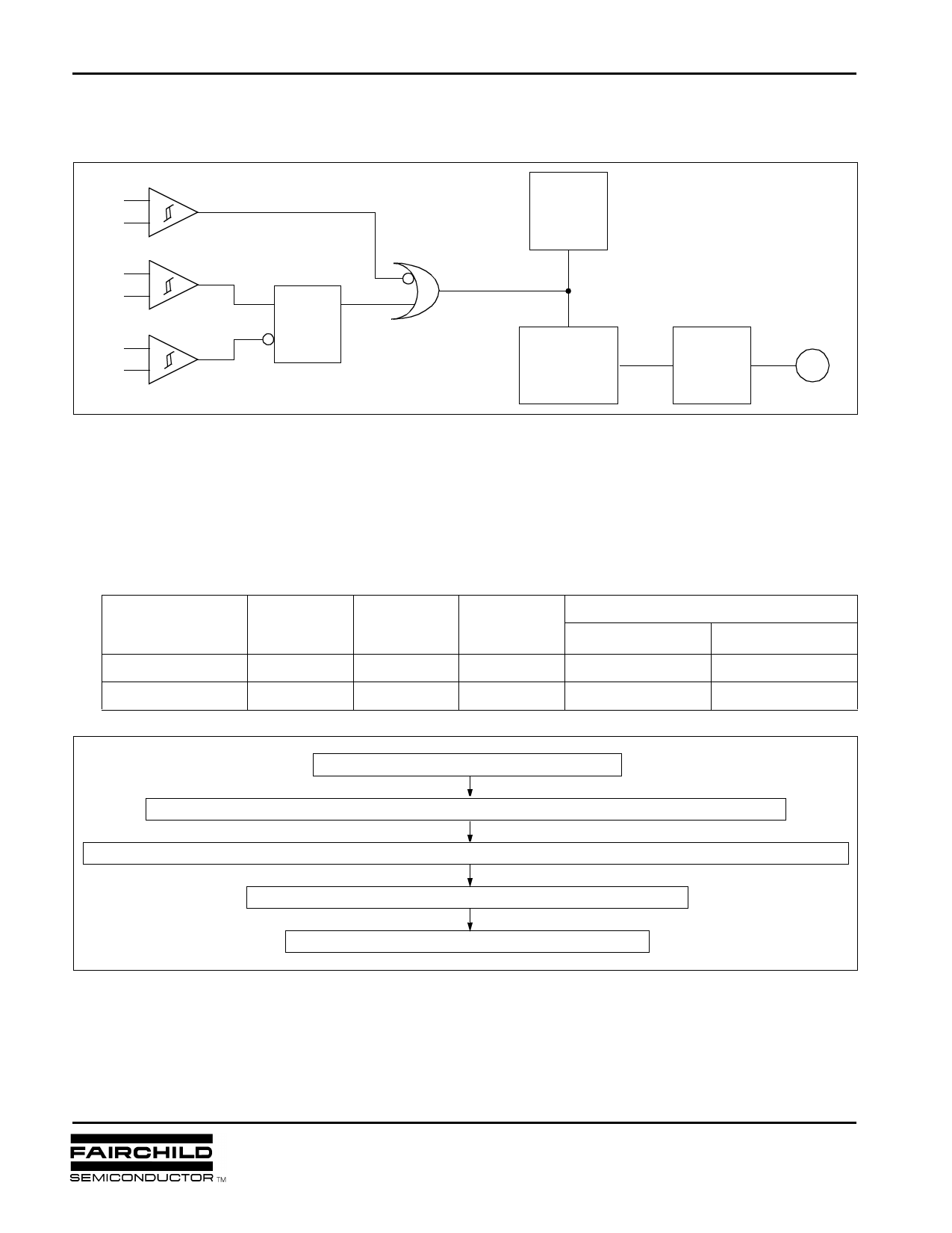
6. REVERSE ROTATION PREVENTION
KA3016D
EC
+
ECR
−
H2+
+
H2−
−
H3+
+
H3−
−
D
Q
CK
D-F/F
Low Active
A
Current
Sense
Amp
Gain
Controller
Driver
M
• When the output of the OR Gate, A is low, it steers all the output current of the current sense amp makes the
current delivered to the gain controller zero. Thus the output current of the driver becomes zero and the motor
is stopped.
• As in the state of the forward rotation, the D-F/F output, Q is high and the motor rotates normally. At this state if
the control input is changed such that EC>ECR, then the motor rotates slowly more and more by the reverse
commutation in the driver. At the moment that the motor rotates in reverse direction, the D-F/F output becomes
low and the OR gate output, thus, becomes low. This prevents the motor from rotating in reverse direction.
The operation principle is shown in the table and the flow chart..
Rotation
Forward
H2
H3
D-F/F
Reverse rotation preventer
(Q)
EC>ECR
EC>ECR
H
H→L
H
Forward
−
Reverse
L
H→L
L
−
Brake and stop
Forward rotation at EC < ECR
Rotating speed is decreased due to reverse torque at EC >ECR. (Motor still rotates forward)
At the moment that the motor rotates in reverse, the reverse rotation preventer makes the output power transistor open.
Rotating reverse at short time due to motor inertia
Stop within 1/6 turn reverse rotating
MIC-99D001
11
January 1999
Share Link: 