AD9558 データシートの表示(PDF) - Analog Devices
部品番号
コンポーネント説明
メーカー
AD9558 Datasheet PDF : 104 Pages
| |||
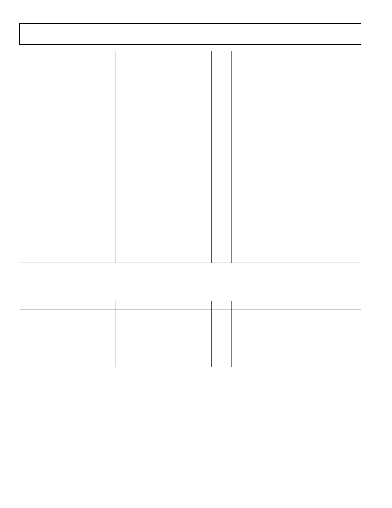
AD9558
Parameter
Min
OUTPUT TIMING SKEW
Between OUT0 and OUT1
Between OUT0 and OUT3
Between OUT0 and OUT5
Between OUT1 and OUT2
(OUT1 and OUT2 Share the
Same Divider)
Between OUT3 and OUT4
(OUT3 and OUT4 Share the
Same Divider)
Across All OUT0 to OUT4 HSTL
Across All OUT0 to OUT4 LVDS
Additional Delay on One Driver by
Changing Its Logic Type
HSTL to LVDS
−5
HSTL to 1.8 V CMOS
−5
HSTL to 3.3 V CMOS, Strong Mode
OUT0 CMOS to OUT1 HSTL
OUT0 CMOS to OUT3 HSTL
OUT0 CMOS to OUT4 HSTL
OUT0 CMOS to OUT5 HSTL
1 The listed values are for the slower edge (rise or fall).
Typ
Max
10
70
105
222
1.39
1.76
1
12
1
24
105
235
100
235
+1
+5
0
+5
3.53
3.59
3.55
3.65
3.56
3.68
4.84
5.1
TIME DURATION OF DIGITAL FUNCTIONS
Table 11.
Parameter
Min
TIME DURATION OF DIGITAL
FUNCTIONS
EEPROM-to-Register Download
Time
Register-to-EEPROM Upload Time
Typ
Max
13
20
138
145
Minimum Power-Down Exit Time
1
Data Sheet
Unit Test Conditions/Comments
10 pF load
ps HSTL mode on both drivers; rising edge only; any
divide value
ps HSTL mode on both drivers; rising edge only; any
divide value
ns HSTL mode on both drivers; rising edge only; any
divide value
ps HSTL mode on both drivers; rising edge only; any
divide value
ps HSTL mode on both drivers; rising edge only; any
divide value
ps HSTL mode on all drivers; rising edge only; any
divide value
ps LVDS mode on all drivers; rising edge only; any
divide value
ps Positive value indicates that the LVDS edge is
delayed relative to HSTL
ps Positive value indicates that the CMOS edge is
delayed relative to HSTL
The CMOS edge is delayed relative to HSTL
ns
ns
ns
ns
Unit Test Conditions/Comments
ms Using default EEPROM storage sequence
(see Register 0x0E10 to Register 0x0E3F)
ms Using default EEPROM storage sequence
(see Register 0x0E10 to Register 0x0E3F)
ms Time from power-down exit to system clock
lock detect
Rev. A | Page 10 of 104
Share Link: 