AD8210(Rev0) データシートの表示(PDF) - Analog Devices
部品番号
コンポーネント説明
メーカー
AD8210 Datasheet PDF : 16 Pages
| |||
MODES OF OPERATION
The AD8210 can be adjusted for unidirectional or bidirectional
operation.
UNIDIRECTIONAL OPERATION
Unidirectional operation allows the AD8210 to measure
currents through a resistive shunt in one direction. The basic
modes for unidirectional operation are ground referenced
output mode and V+ referenced output mode.
In unidirectional operation, the output can be set at the negative
rail (near ground) or at the positive rail (near V+) when the
differential input is 0 V. The output moves to the opposite rail
when a correct polarity differential input voltage is applied. In
this case, full scale is approximately 250 mV. The required
polarity of the differential input depends on the output voltage
setting. If the output is set at ground, then the polarity needs to
be positive to move the output up (see Table 5). If the output is
set at the positive rail, then the input polarity needs to be
negative to move the output down (see Table 6).
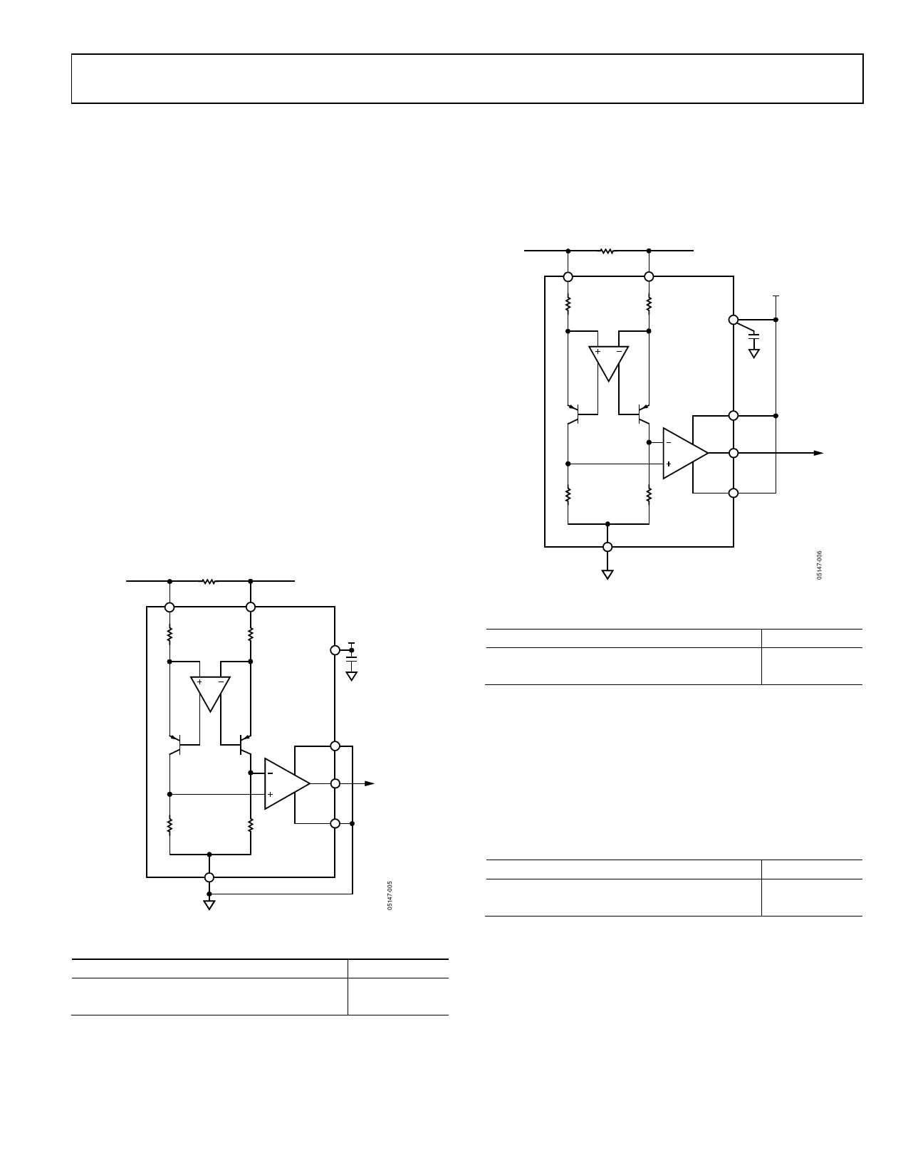
Ground Referenced Output
When using the AD8210 in this mode, both reference inputs
are tied to ground, which causes the output to sit at the negative
rail when the differential input voltage is zero (see Figure 27
and Table 4).
RS
+IN
–IN
VS
AD8210
0.1µF
GND
VREF1
G = +20
VREF2
OUTPUT
Figure 27. Ground Referenced Output
Table 4. V+ = 5 V
VIN (Referred to −IN)
0V
250 mV
VO
0.05 V
4.9 V
AD8210
V+ Referenced Output
This mode is set when both reference pins are tied to the
positive supply. It is typically used when the diagnostic scheme
requires detection of the amplifier and wiring before power is
applied to the load (see Figure 28 and Table 5).
RS
+IN
–IN
VS
AD8210
0.1µF
VREF1
G = +20
OUTPUT
GND
VREF2
Figure 28. V+ Referenced Output
Table 5. V+ = 5 V
VIN (Referred to −IN)
0V
−250 mV
VO
4.9 V
0.05 V
BIDIRECTIONAL OPERATION
Bidirectional operation allows the AD8210 to measure currents
through a resistive shunt in two directions. The output offset
can be set anywhere within the output range. Typically, it is set
at half scale for equal measurement range in both directions. In
some cases, however, it is set at a voltage other than half scale
when the bidirectional current is nonsymmetrical.
Table 6. V+ = 5 V, VO = 2.5 V with VIN = 0 V
VIN (Referred to –IN)
+125 mV
−125 mV
VO
4.9 V
0.05 V
Adjusting the output can also be accomplished by applying
voltage(s) to the reference inputs.
Rev. 0 | Page 11 of 16
Share Link: 