74ALVC125 データシートの表示(PDF) - Philips Electronics
部品番号
コンポーネント説明
メーカー
74ALVC125 Datasheet PDF : 16 Pages
| |||
Philips Semiconductors
Quad buffer/line driver; 3-state
Product specification
74ALVC125
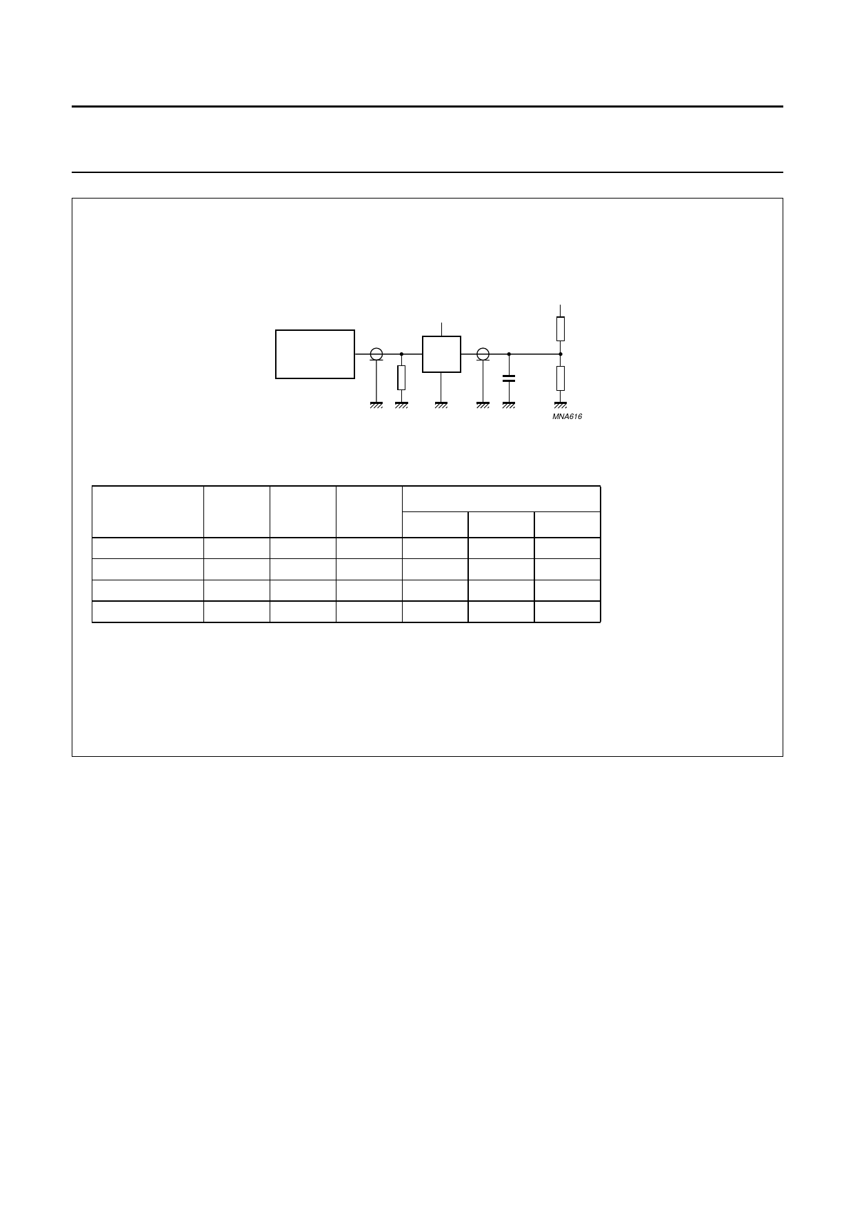
handbook, full pagewidth
VCC
PULSE
VI
GENERATOR
VO
D.U.T.
RT
VEXT
RL
CL
RL
MNA616
VCC
1.65 to 1.95 V
2.3 to 2.7 V
2.7 V
3.0 to 3.6 V
VI
VCC
VCC
2.7 V
2.7 V
CL
30 pF
30 pF
50 pF
50 pF
RL
1 kΩ
500 Ω
500 Ω
500 Ω
VEXT
tPLH/tPHL tPZH/tPHZ tPZL/tPLZ
open
open
GND
GND
2 × VCC
2 × VCC
open
GND
6V
open
GND
6V
Definitions for test circuit
RL = Load resistor.
CL = Load capacitance including jig and probe capacitance.
RT = Termination resistance should be equal to the output impedance Zo of the pulse generator.
Fig.7 Load circuitry for switching times.
2002 Nov 18
9
Share Link: 