74AHC574PWDH データシートの表示(PDF) - NXP Semiconductors.
部品番号
コンポーネント説明
メーカー
74AHC574PWDH Datasheet PDF : 20 Pages
| |||
Philips Semiconductors
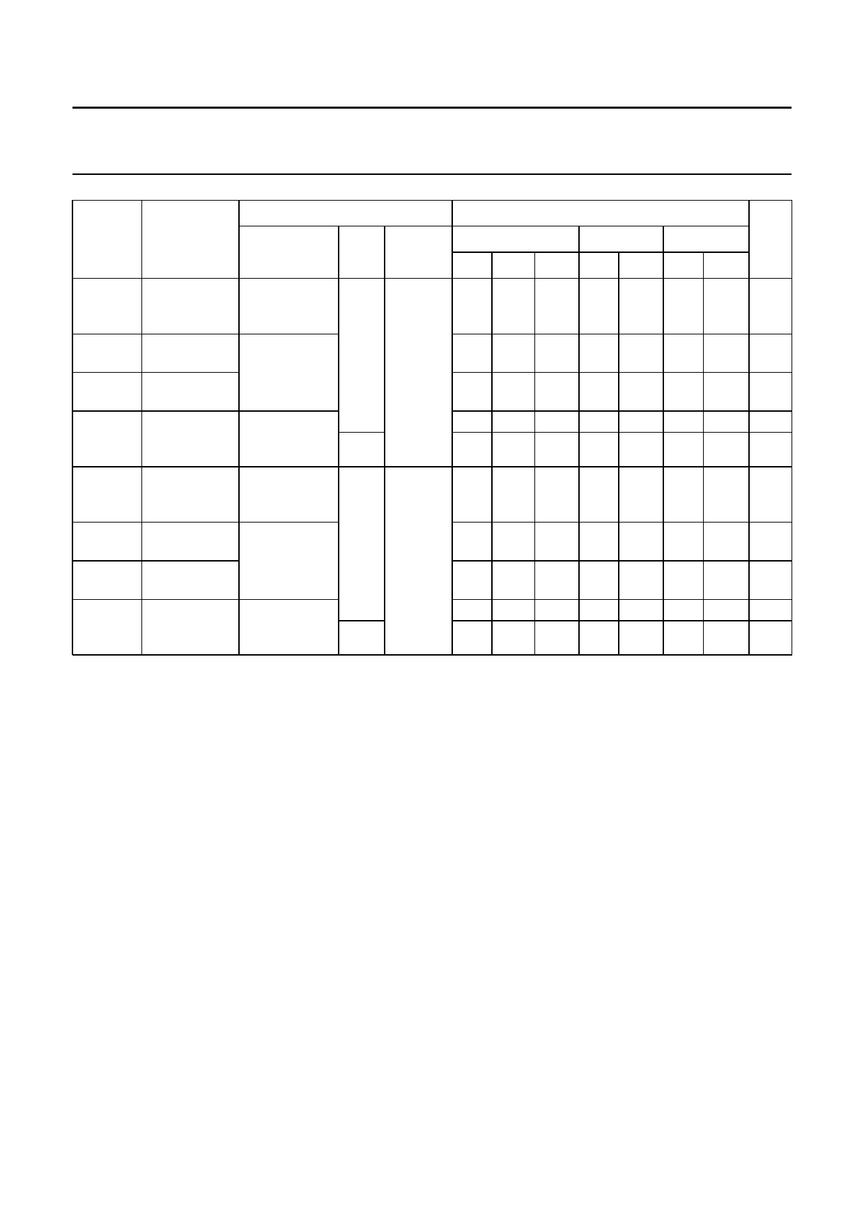
Octal D-type flip-flop; positive edge-trigger; 3-state
Product specification
74AHC574;
74AHCT574
TEST CONDITIONS
Tamb (°C)
SYMBOL PARAMETER
WAVEFORMS CL
+25
−40 to +85 −40 to +125 UNIT
VCC (V)
MIN. TYP. MAX. MIN. MAX. MIN. MAX.
tW
clock pulse see Figs 6
50 pF 3.0 to 3.6 5.0 −
−
5.0 −
5.0 −
ns
width
and 9
HIGH or LOW
tsu
setup time see Figs 8
Dn to CP
and 9
th
hold time
Dn to CP
fmax
maximum
see Figs 6
clock pulse and 9
15 pF
frequency
3.5 −
−
1.5 −
−
50 75 −
80 125 −
3.5 −
1.5 −
45 −
65 −
3.5 −
1.5 −
45 −
65 −
ns
ns
MHz
MHz
tW
clock pulse see Figs 6
50 pF 4.5 to 5.5 5.0 −
−
5.0 −
5.0 −
ns
width
and 9
HIGH or LOW
tsu
setup time see Figs 8
Dn to CP
and 9
th
hold time
Dn to CP
fmax
maximum
see Figs 6
clock pulse and 9
15 pF
frequency
3.0 −
−
1.5 −
−
85 115 −
130 180 −
3.0 −
1.5 −
75 −
110 −
3.0 −
1.5 −
75 −
110 −
ns
ns
MHz
MHz
Notes
1. Typical values at VCC = 3.3 V.
2. Typical values at VCC = 5.0 V.
1999 Jun 16
10
Share Link: 