2SC2655 データシートの表示(PDF) - Toshiba
部品番号
コンポーネント説明
メーカー
2SC2655 Datasheet PDF : 5 Pages
| |||
2SC2655
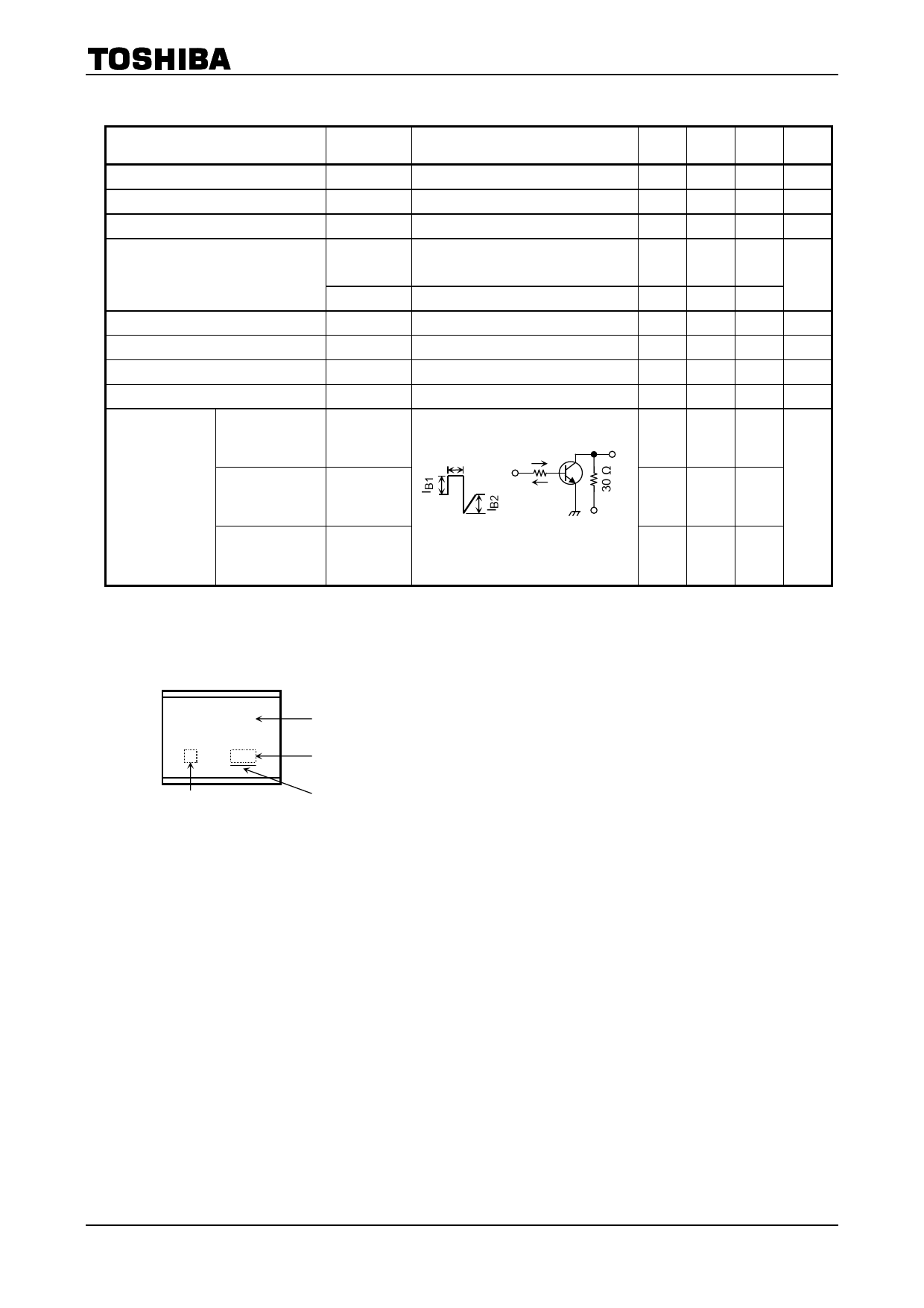
Electrical Characteristics (Ta = 25°C)
Characteristics
Collector cut-off current
Emitter cut-off current
Collector-emitter breakdown voltage
DC current gain
Collector-emitter saturation voltage
Base-emitter saturation voltage
Transition frequency
Collector output capacitance
Symbol
Test Condition
ICBO
VCB = 50 V, IE = 0
IEBO
VEB = 5 V, IC = 0
V (BR) CEO IC = 10 mA, IB = 0
hFE (1)
VCE = 2 V, IC = 0.5 A
(Note)
hFE (2)
VCE (sat)
VBE (sat)
fT
Cob
VCE = 2 V, IC = 1.5 A
IC = 1 A, IB = 0.05 A
IC = 1 A, IB = 0.05 A
VCE = 2 V, IC = 0.5 A
VCB = 10 V, IC = 0, f = 1 MHz
Min Typ. Max Unit
―
―
1.0
μA
―
―
1.0
μA
50
―
―
V
70
―
240
40
―
―
―
―
0.5
V
―
―
1.2
V
― 100 ― MHz
―
30
―
pF
Turn-on time
ton
Output
―
0.1
―
20 μs Input IB1
Switching time Storage time
tstg
IB2
30 V
Fall time
tf
IB1 = −IB2 = 0.05 A, duty cycle ≤ 1%
Note: hFE (1) classification O: 70 to 140, Y: 120 to 240
―
1.0
―
μs
―
0.1
―
Marking
C2655
Characteristics
indicator
Part No. (or abbreviation code)
Lot No.
A line indicates
lead (Pb)-free package or
lead (Pb)-free finish.
2
2006-11-09
Share Link: 