G5V-212VDC Ver la hoja de datos (PDF) - OMRON Corporation
Número de pieza
componentes Descripción
fabricante
G5V-212VDC Datasheet PDF : 4 Pages
| |||
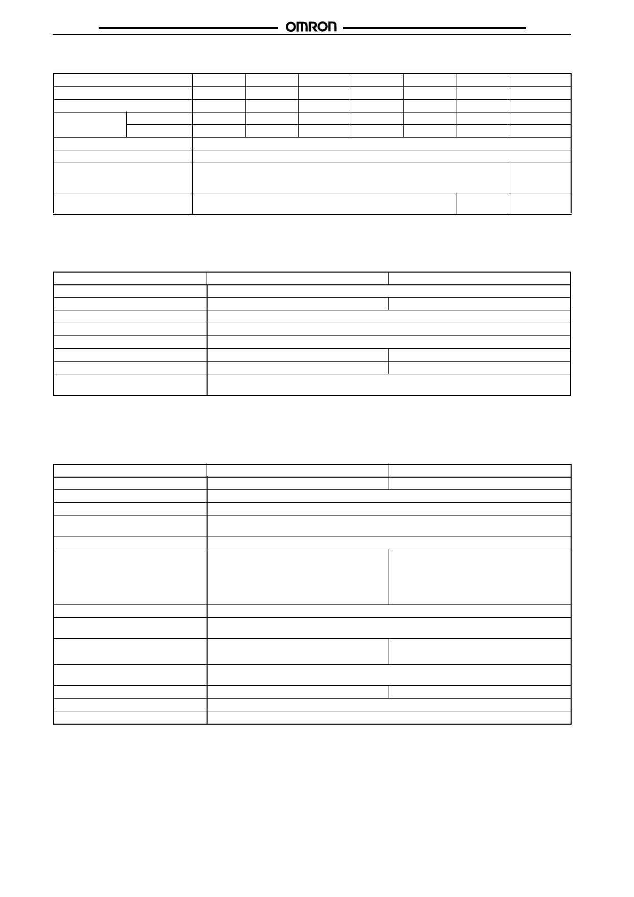
G5V-2
G5V-2
High Sensitivity Models
Rated voltage
Rated current
Coil resistance
Coil inductance Armature ON
(H) (ref. value) Armature OFF
Must operate voltage
Must release voltage
Max. voltage
3 VDC
5 VDC
6 VDC
50 mA
30 mA
25 mA
60 Ω
166.7 Ω
240 Ω
0.18
0.46
0.70
0.57
0.71
0.97
75% max. of rated voltage
5% min. of rated voltage
180% of rated voltage at 23°C
Power consumption
Approx. 150 mW
9 VDC
16.7 mA
540 Ω
1.67
2.33
12 VDC
12.5 mA
960 Ω
2.90
3.99
24 VDC
8.33 mA
2,880 Ω
6.72
9.27
48 VDC
6.25 mA
7,680 Ω
20.1
26.7
Approx.
200 mW
150% of rated
voltage at
23°C
Approx.
300 mW
Note: 1. The rated current and coil resistance are measured at a coil temperature of 23°C with a tolerance of ±10%.
2. Operating characteristics are measured at a coil temperature of 23°C.
3. The maximum voltage is the highest voltage that can be imposed on the relay coil.
I Contact Ratings
Item
Standard models
High sensitivity models
Load
Resistive load (cosφ = 1)
Rated load
0.5 A at 125 VAC; 2 A at 30 VDC
0.5 A at 125 VAC; 1 A at 24 VDC
Contact material
Ag + Au-clad
Rated carry current
2A
Max. switching voltage
125 VAC, 125 VDC
Max. switching current
2A
1A
Max. switching power
62.5 VA, 60 W
62.5 VA, 24 W
Failure rate (reference value)
(See note.)
0.01 mA at 10 mVDC
Note:
P level: λ60 = 0.1 x 10⁻⁶/operation
This value was measured at a switching frequency of 120 operations/min and the criterion of contact resistance is 50 Ω. This value
may vary depending on the switching frequency and operating environment. Always double-check relay suitability under actual op-
erating conditions.
I Characteristics
Item
Contact resistance (See note 1.)
Operate time
Release time
Max. operating frequency
Insulation resistance (See note 2.)
Dielectric strength
Impulse withstand voltage
Vibration resistance
Shock resistance
Endurance
Ambient temperature
Ambient humidity
Weight
Standard models
High sensitivity models
50 mΩ max.
100 mΩ max.
7 ms max.
3 ms max.
Mechanical: 36,000 operations/hr
Electrical: 1,800 operations/hr (under rated load)
1,000 MΩ min. (at 500 VDC)
1,000 VAC, 50/60 Hz for 1 min between coil
and contacts
1,000 VAC, 50/60 Hz for 1 min between con-
tacts of different polarity
750 VAC, 50/60 Hz for 1 min between contacts
of same polarity
1,000 VAC, 50/60 Hz for 1 min between coil
and contacts
1,000 VAC, 50/60 Hz for 1 min between con-
tacts of different polarity
500 VAC, 50/60 Hz for 1 min between contacts
of same polarity
1,500 V (10 x 160 µs) between coil and contacts (conforms to FCC Part 68)
Destruction: 10 to 55 to 10 Hz, 0.75-mm single amplitude (1.5-mm double amplitude)
Malfunction: 10 to 55 to 10 Hz, 0.75-mm single amplitude (1.5-mm double amplitude)
Destruction: 1,000 m/s2 (approx. 100G)
Malfunction: 200 m/s2 (approx. 20G)
Destruction: 1,000 m/s2 (approx. 100G)
Malfunction: 100 m/s2 (approx. 10G)
Mechanical: 15,000,000 operations min. (at 36,000 operations/hr)
Electrical: 100,000 operations min. (at 1,800 operations/hr)
Operating: −25°C to 65°C (with no icing)
Operating: −25°C to 70°C (with no icing)
Operating: 5% to 85%
Approx. 5 g
Note:
Note:
The above values are initial values.
1. The contact resistance was measured with 10 mA at 1 VDC with a voltage drop method.
2. The insulation resistance was measured with a 500-VDC megohmmeter applied to the same parts as those used for checking
the dielectric strength.
106
Share Link: 