STK672-060 Ver la hoja de datos (PDF) - SANYO -> Panasonic
Número de pieza
componentes Descripción
fabricante
STK672-060
SANYO -> Panasonic
STK672-060 Datasheet PDF : 19 Pages
| |||
STK672-060
Power-on reset
The application must perform a power-on reset operation when VCC2 power is first applied to this hybrid IC.
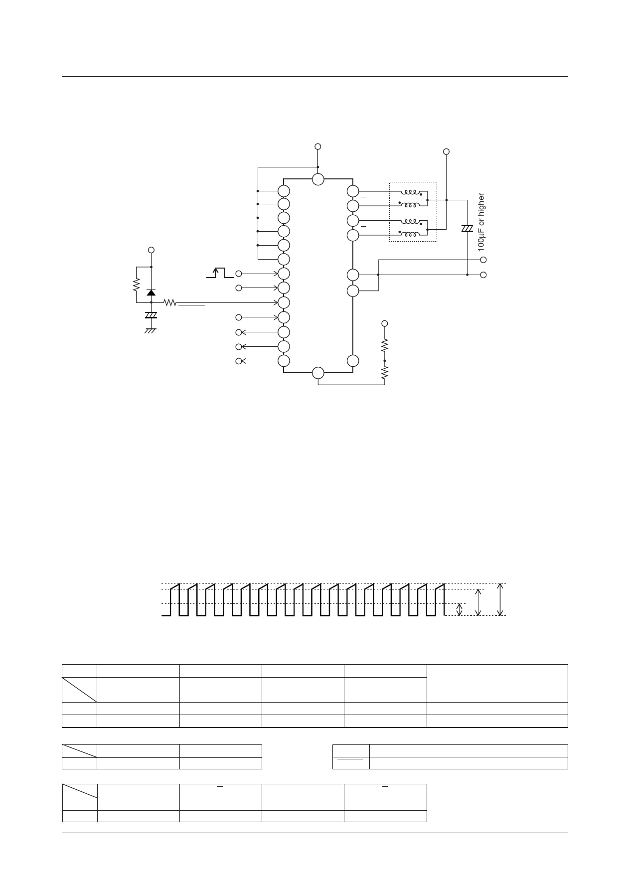
Application circuit that used 2W1-2 phase excitation (microstepping operation) mode
VCC2=5V
VCC1=10V to 45V
Simple power-on reset circuit
(This circuit cannot be used to
detect drops in the supply voltage.)
VCC2=5V
VF≈0.3V
CLK
ENABLE
1kΩ
+ RESET
RET
MoI
Mo1
Mo2
Two-phase stepping motor
7
9
6A
10
5A
11
2B
+
12
1B
143
15
SG
14 STK672-060 3
PG
18
16
17
19
20
21
22
4
VCC2=5V
8 RoX
Ro1
Vref
Ro2
A value of about 100 Ω is
recommended for Ro2 to minimize
the influence of the 6 kΩ internal
resistance of the Vref pin.
RoX: Input impedance of 6 kΩ ±30%
ITF02269
Motor Current Setting Procedure
The motor current IOH is set by the voltage on pin 8, Vref. The following formulas show the relationship between IOH
and Vref:
RoX = (Ro2 × 6 kΩ) ÷ (Ro2 + 6 kΩ)....................(1)
Vref = VCC2 × RoX ÷ (Ro1 + RoX) .....................(2)
IOH =
—1
K
×
—Vr—ef
Rs
...................................................(3)
K: 7.66 (voltage divider ratio),
Rs: 0.22 Ω (This is the hybrid IC's internal current detection resistor. It has a tolerance of ±3%.)
Motor currents range from the setting current (0.05 to 0.1 A) due to the frequency of the duty cycle set by the oscillator to
the current given in the allowable operating ranges (IOH = 1.2 A).
OA
Motor Current Waveform
Function Table
M2
M1
M3
1
0
0
0
2 phase excitation
1-2 phase excitation
0
1
1
1
0
1
1-2 phase excitation W1-2 phase excitation 2W1-2 phase excitation
W1-2 phase excitation 2W1-2 phase excitation 4W1-2 phase excitation
Ioave
IOL IOH
A13262
Phase switching CLK edge timing
Rising edge only
Both rising and falling edges
CWB
Mo1
Mo2
Forward
0
A
1
0
Reverse
1
A
0
0
ENABLE The motor current is cut when this pin is set to the low level.
RESET
Active low
B
B
0
1
1
1
No. 7441-6/19
Share Link: 