GS9035ACPJE3 Ver la hoja de datos (PDF) - Gennum -> Semtech
Número de pieza
componentes Descripción
fabricante
GS9035ACPJE3 Datasheet PDF : 14 Pages
| |||
2. FREQUENCY ACQUISITION
The core PLL is able to lock if the incoming data rate and
the PLL clock frequency are within the PLL capture range
(which is slightly larger than the loop bandwidth). To assist
the PLL to lock to data rates outside of the capture range,
the GS9035A uses a frequency acquisition circuit.
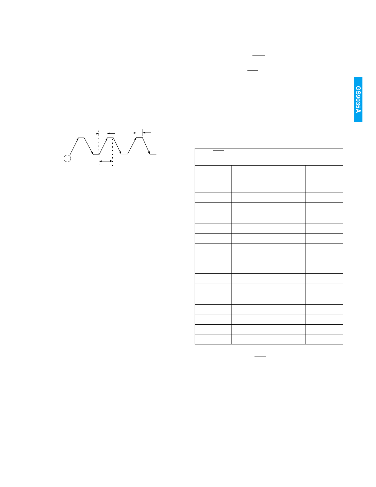
The frequency acquisition circuit sweeps the VCO control
voltage such that the VCO frequency changes from -10% to
+10% of the center frequency. Figure 13 shows a typical
sweep waveform.
tswp
tsys
4. AUTO/MANUAL DATA RATE SELECT
The GS9035A can operate in either auto or manual data
rate select mode. The mode of operation is selected by a
single input pin (AUTO/MAN).
4.1 Auto Mode (AUTO/MAN = 1)
In auto mode, the GS9035A uses a 3-bit counter to
automatically cycle through five (SMPTE=1) or three
(SMPTE=0) different divider moduli as it attempts to acquire
lock. In this mode, the SS[2:0] pins are outputs and indicate
the current value of the divider moduli according to Table 2.
Note that for SMPTE = 0 and divider moduli of 2 and 4, the
PLL can correctly lock for two values of SS[2:0].
VLF
A
Tcycle
Tcycle = tswp + tsys
Fig. 13 Typical Sweep Form
The VCO frequency starts at point A and sweeps up
attempting to lock. If lock is not established during the up
sweep, the VCO is then swept down. The system is
designed such that the probability of locking within one
cycle period is greater than 0.999. If the system does not
lock within one cycle period, it will attempt to lock in the
subsequent cycle. In manual mode, the divider modulus is
fixed for all cycles. In auto mode, each subsequent cycle is
based on a different divider moduli as determined by the
internal 3-bit counter.
The average sweep time, tswp, is determined by the loop
filter component, CLF1, and the charge pump current, ΙCP:
tswp =
4 CLF1
3 ΙLF1
[seconds]
The nominal sweep time is approximately 121µs when
CLF1 = 15nF and ΙCP = 165µA (RVCO = 365Ω).
An internal system clock determines tsys (see section 7,
Logic Circuit).
3. LOGIC CIRCUIT
The GS9035A is controlled by a finite state logic circuit which
is clocked by an asynchronous system clock. That is, the
system clock is completely independent of the incoming data
rate. The system clock runs at low frequencies, relative to the
incoming data rate, and thus reduces interference to the PLL.
The period of the system clock is set by the COSC capacitor
and is
tsys = 9.6 x 10⁴ x COSC [seconds]
The recommended value for tsys is 450µs (COSC = 4.7nF).
TABLE 2: Data Rate Indication in Auto Mode
AUTO/MAN = 1 (Auto Mode)
ƒH, ƒL = VCO center frequency as per Figure 12
SMPTE
SS[2:0]
DIVIDER
MODULI
1
000
4
1
001
2
1
010
2
1
011
1
1
100
1
1
101
-
1
110
-
1
111
-
0
000
4
0
001
4
0
010
2
0
011
2
0
100
1
0
101
-
0
110
-
0
111
-
PLL CLOCK
ƒH/4
ƒL/2
ƒH/2
ƒL
ƒH
-
-
-
ƒH/4
ƒH/4
ƒH/2
ƒH/2
ƒH
-
-
-
4.2 Manual Mode (AUTO/MAN = 0)
In manual mode, the GS9035A divider moduli is fixed. In
this mode, the SS[2:0] pins are inputs and set the divider
moduli according to Table 3.
GENNUM CORPORATION
8 of 14
522 - 41 - 08
Share Link: 