LF48908QC31 Ver la hoja de datos (PDF) - LOGIC Devices
Número de pieza
componentes Descripción
fabricante
LF48908QC31 Datasheet PDF : 16 Pages
| |||
DEVICES INCORPORATED
LF48908
Two Dimensional Convolver
be ignored. If the LF48908 is not in
active operation or if the innactive
Coefficient Register is being written to
during active operation.
Cascade Operation
The Cascade Input lines (CASI15-0)
and Cascade Output lines (CASO7-0)
are used to allow convolutions of
kernel sizes larger than 3 x 3. The
Cascade Input lines are also used to
allow convolutions on row lengths
longer than 1024 pixels. The Cascade
Mode Bit (Bit 0) of the Initialization
Register determines the function of
the Cascade Input lines. If the Cas-
cade Mode Bit is a “0”, then the
Cascade Input lines are to be used to
cascade multiple LF48908s together to
perform convolutions of larger kernel
sizes. CASI15-0 will be left shifted (by
an amount determined by bits 7 and 8
of the Initialization Register) and then
added to DOUT19-0. Cascading is
accomplished by connecting CASO7-0
and DOUT19-0 of one LF48908 to
DIN7-0 and CASI15-0 respectively of
another LF48908. If the Cascade
Mode Bit is a “1”, then the Cascade
Input lines are to be used with exter-
nal row buffers to allow for longer
row lengths. In this mode, the Cas-
cade Input lines are split into two 8-bit
data busses (CASI15-8 and CASI7-0)
which are fed directly into the multi-
plier array.
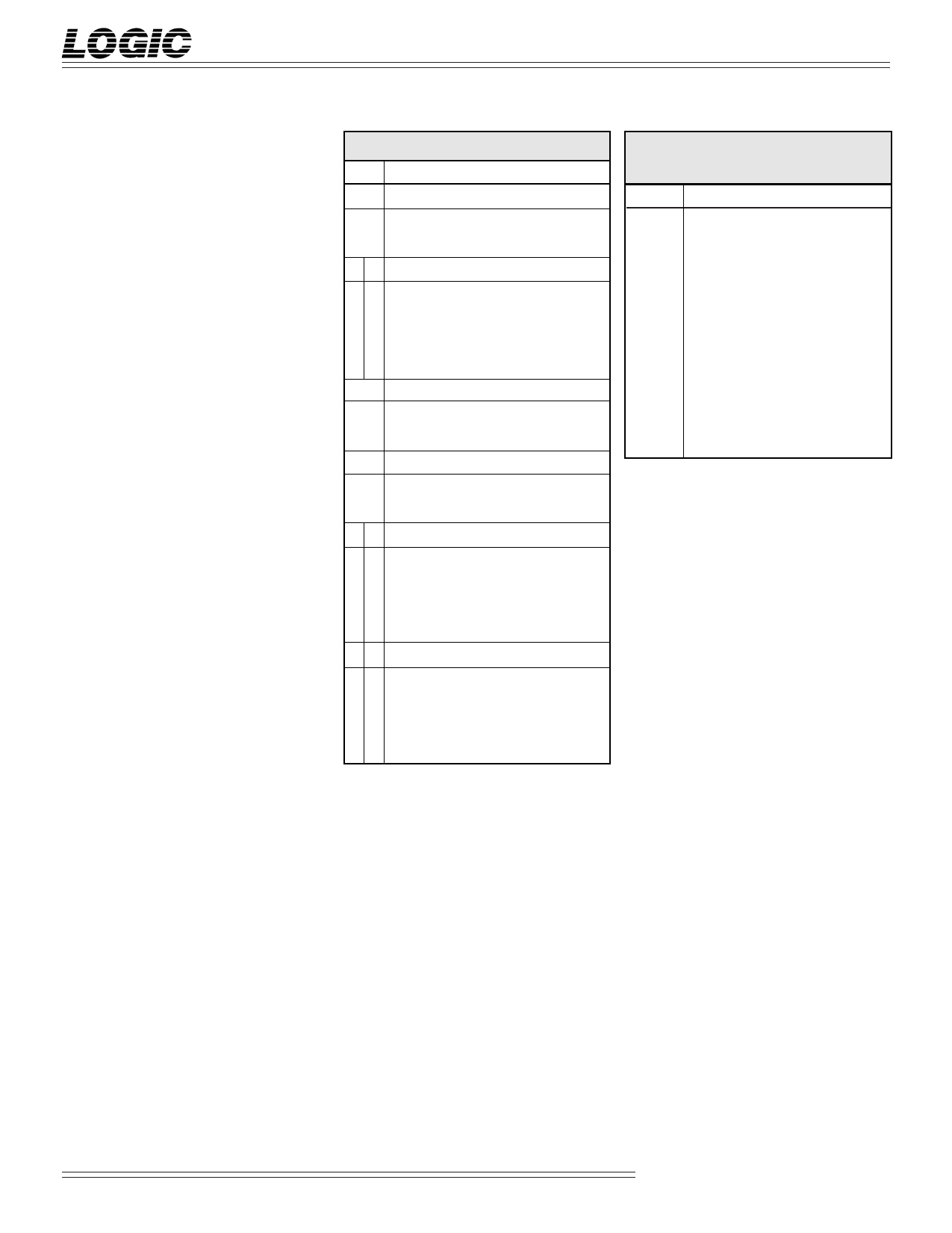
TABLE 3. INITIALIZATION REGISTER
BIT
FUNCTION
0
CASCADE MODE
0 Multiplier input from internal row buffers
1 Multiplier input from external buffers
21
INPUT DATA DELAY
0 0 No data delay registers used
0 1 One data delay register used
1 0 Two data delay registers used
1 1 Three data delay registers used
3
INPUT DATA FORMAT
0 Unsigned integer format
1 Two’s complement format
4
COEFFICIENT DATA FORMAT
0 Unsigned integer format
1 Two’s complement format
65
OUTPUT ROUNDING
0 0 No rounding
0 1 Round to 16 bits (i.e. DOUT19-4)
1 0 Round to 8 bits (i.e. DOUT19-12)
1 1 Not valid
87
CASI15-0 INPUT SHIFT
0 0 No shift
0 1 Shift CASI15-0 left two
1 0 Shift CASI15-0 left four
1 1 Shift CASI15-0 left eight
TABLE 4. CONTROL LOGIC
ADDRESS MAP
A2-0
FUNCTION
000 Load Row Buffer Length
Register
1
001 Load ALU Microcode Register
010 Load Coefficient Register 0
2
011 Load Coefficient Register 1
100 Load Initialization Register
101 Select Coefficient Register 0
3
for Internal Processing
110 Select Coefficient Register 1
for Internal Processing
4
111 No Operation
5
6
7
8
9
10
11
Video Imaging Products
7
08/9/2000–LDS.48908-J
Share Link: 